


CST6107 Overview:
CST6107 is a single channel brushless DC motor driver chip. The maximum continuous output current can reach 1.8A, and the peak value can reach 2.5A. The chip has a built-in power MOS full bridge drive, which can drive forward, backward, stop and brake. At the same time, it has a built-in over temperature protection circuit to ensure the safety of the chip operation.
The full bridge drive architecture and drive mode can save the peripheral filter circuit, save the cost and facilitate the application. The extremely small circuit static power consumption (less than 1uA) can make CST6107 more widely used.
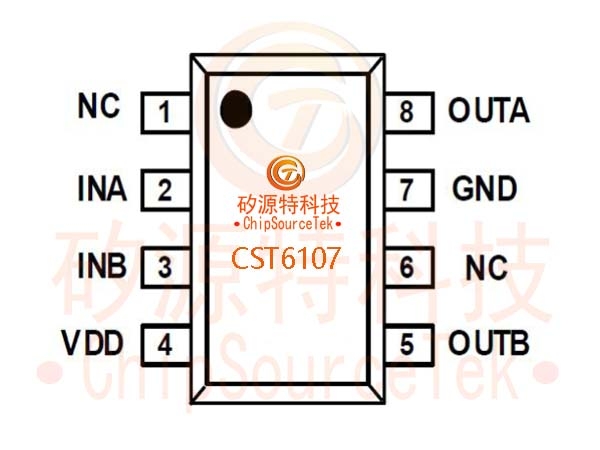
CST6107 provides DFN8-2mm * 2mm * 0.55mm package.
CST6107 Features:
Single channel full bridge power drive structure
Operating voltage range (1.5V~7V)
The maximum continuous output current can reach 1.8A
The maximum peak output current can reach 2.5A
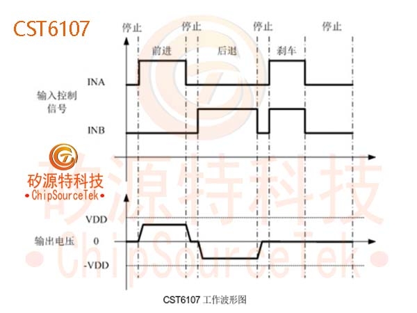
Including forward/reverse/stop/brake functions
Very low quiescent current (typ. 0.1uA)
Low on resistance (0.4 Ω/1000mA)
Built in thermal protection function with hysteresis effect (TSD)
Packaging form: DFN8-2mm * 2mm * 0.55mm
CST6107 Product Application:
DC brush motor drive for toys
Micro robot equipment
.jpg)
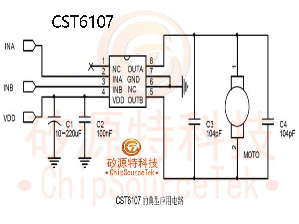
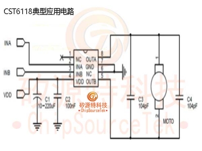
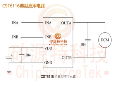
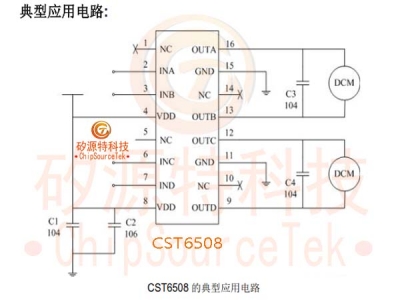
CST6107 typical application circuit:
.jpg)
Note: 1. The C4/104P capacitor in the figure is connected to the motor in parallel rather than on the PCB. If the motor is not connected in parallel, a position can be reserved on the PCB.
2. Compared with the general application of the same type of products in the market, C1, C2 and C3 in the figure can be omitted, peripheral devices are reduced, and costs are saved.
CST6107 Special precautions:
In different applications, only one C1 and C2 can be considered: in 4.5V applications, it is recommended to use one 1uF or more, and use a chip capacitor; A large capacitance 220uF+100nF chip capacitor is recommended for 6V applications; C1 and C2 shall be placed close to the VDD pin of the IC, and the connection between the negative pole of the capacitor and the GND terminal of the IC shall be as short as possible. That is, although the capacitance is near, the wiring and routing are far away. When there is a large capacitor on the application board filtering for other chips and it is far away from CST6107, it is also necessary to place a small capacitor on the VDD pin of CST6107 according to the above requirements. In the figure, C4 (100nF) capacitor is preferentially connected to the motor. When it is not convenient to weld this capacitor on the motor, it is placed on the PCB (i.e. C3).
The general low-voltage application of CST6107 can eliminate C1, C2 and C3 capacitors. If the power supply fluctuates greatly or the output drive current is large, it is recommended to add C2 and C3 capacitors. It can be selected according to the actual situation.
CST6107 is sensitive to static electricity. Anti static measures shall be taken during packaging, transportation and processing.
It is recommended that the current value at the moment of motor startup should not exceed 2.5A of the peak value of the chip.
The motor locked motor has different peak currents due to different motors. If the motor locked peak current is too large, the IC may be burned.
.jpg)
.jpg)


 Business consulting

 13823761625
 Mail me