


Implementation of Brushless DC Motor Drive Control Design for Four Axis Aircraft
Time:2023-05-21
Views:902
The four axis aircraft is a popular technology product in both professional and non professional fields recently. The following article designs and develops a three-phase six arm full bridge drive circuit and control program for the drive control of the sensorless brushless DC motor of a four axis aircraft. The design uses an ATMEGA16 microcontroller as the control core, and utilizes the zero crossing detection of the back electromotive force to alternately conduct six MOSFETs in the driving circuit to achieve commutation; The DC brushless motor control program completes MOSFET power on self check, motor start software control, PWM motor speed control, and circuit protection functions. This design has a simple circuit structure, low cost, and stable and reliable motor operation, achieving continuous motor operation.

In recent years, the research and application scope of four-axis aircraft has gradually expanded, using four brushless DC motors as its power source. Brushless DC motor is an external rotor structure, which directly drives the propeller to rotate at high speed.
The driving and control methods of brushless mainstream motors are mainly divided into two types: control methods with position sensors and control methods without position sensors. Due to the requirements of a brushless DC motor controller in a four axis aircraft, which requires small size, light weight, high efficiency and reliability, a position sensorless brushless DC motor is adopted. This article uses the Langyu X2212 kv980 brushless DC motor.
The brushless DC motor drive control system includes two parts: the drive circuit and the system program control. The three-phase full bridge drive circuit is composed of the switching characteristics of power transistors, and then DSP is used as the main control chip. With its powerful computing and processing capabilities, the motor can be started and controlled. However, the circuit structure is complex, high cost, and lacks economy.
The commutation of DC brushless motors adopts the back electromotive force zero crossing detection method, and once the back electromotive force zero crossing of the third phase is detected, preparations are made for commutation. The zero crossing detection of the back electromotive force adopts the virtual neutral point method, which determines the rotor position by detecting the zero crossing of the back electromotive force in each phase of the motor. The theory of motor current commutation based on the voltage variation law of the three-phase winding terminal of the motor can greatly improve the control accuracy of the system.
The driving circuit of the brushless DC motor in this article adopts a three-phase six arm full bridge circuit, and the management and control chip of the control circuit is implemented using an ATmega 16 microcontroller to fully utilize its high-performance and resource rich characteristics. Therefore, the peripheral circuit structure is simple. The brushless DC motor adopts software startup and PWM speed control methods to achieve motor startup and stable operation, greatly improving the speed regulation and control performance of the brushless DC motor for four-axis aircraft.
1 three-phase six arm full bridge drive circuit
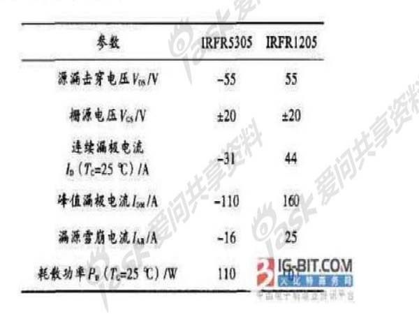
The brushless DC motor drive control circuit is shown in Figure 1. The circuit adopts a three-phase six arm full bridge drive method, which can reduce current fluctuations and torque pulsation, resulting in a larger torque output of the motor. In the motor drive section, six power field-effect transistors are used to control the output voltage. The power supply voltage of the DC brushless motor drive circuit in the four axis aircraft is 12 V. In the drive circuit, IRFR5305 (P-channel) from IR company is used for Q1 to Q3, and IRFR1205 (N-channel) is used for Q4 to Q6. The field-effect transistor contains a continuous current diode, which provides a current path when the field-effect transistor is turned off to avoid reverse breakdown of the tube. Its typical characteristic parameters are shown in Table 1. T1~T3 use PDTC143ET to provide driving signals for the field-effect transistor.
Table 1 MOSFET Tube Parameters
From Figure 1, it can be seen that A1~A3 provides a three-phase full bridge upper bridge arm gate drive signal, which is connected to the hardware PWM drive signal of the ATMEGA16 microcontroller. By changing the duty cycle of the PWM signal, motor speed control is achieved; B1~B3 provide the gate drive signal of the lower bridge arm, directly provided by the I/O port of the microcontroller, with two states of conduction and cutoff.
Figure 1: Three-phase Six Arm Full Bridge Drive Circuit of Brushless DC Motor
The brushless DC motor drive control adopts a three-phase six state control strategy. The power transistor has six triggering states, with only two tubes conducting each time and reversing every 60 ° electrical angle. If the AB phase is conducting at a certain moment, the C phase will stop and there will be no current output. Based on the detected motor rotor position, the microcontroller utilizes the switching characteristics of MOSFETs to achieve power-on control of the motor. For example, when Q1 and Q5 are turned on, AB phase is conductive, and the current flow direction is power positive → Q1 → winding A → winding B → Q5 → power negative. Similarly, when the MOSFET opening sequence is Q1Q5, Q1Q6, Q2Q6, Q2Q4, Q3Q4, Q3Q5, as long as accurate commutation is carried out at the appropriate time, continuous operation of the brushless DC motor can be achieved.
|
Disclaimer: This article is transferred from other platforms and does not represent the views and positions of this site. If there is any infringement or objection, please contact us to delete it. thank you! |


 Business consulting

 13823761625
 Mail me