


How to use tactile devices to improve the perception of human-computer interface
Time:2022-09-23
Views:1654
By: Jeff Shepard
The demand for more efficient human machine interface (HMI) and higher perception is driving the adoption of touch devices in industrial 4.0 applications, automobiles, medical and on-site emergency systems, Internet of Things (IoT) devices, wearable devices and other consumer electronic devices. For example, tactile devices can provide feedback in medical training and patient rehabilitation systems based on VR (virtual reality) or AR (augmented reality), or provide enhanced alerts on the steering wheel to inform drivers of potential unsafe conditions. Touch devices are also used in combination with other HMI technologies (such as sound) to provide a more immersive effect and a more realistic sensory interface.
Designers will face some challenges when using tactile devices, including: selecting the correct tactile technology (eccentric rotating mass (ERM) or linear resonant actuator (LRA)), correctly integrating it into the system to achieve the required feedback level, driving tactile devices, and understanding how to test the vibration, noise performance and reliability of tactile devices.
This paper first briefly reviews the benefits that tactile feedback can bring to several application scenarios, and then introduces the options of tactile technology and examples of real tactile devices from PUI Audio. This paper discusses how to integrate tactile devices into the system, including an example of tactile driver IC, and finally introduces the testing methods of vibration and noise performance in detail.
Multi sensory interface
Tactile devices are increasingly being used in combination with visual and auditory feedback to create a multisensor environment and enhance human-computer interaction. Touch interfaces may include clothing, gloves, touch screens, and other objects, such as mobile devices and computer mice.
Multi sensory interaction is particularly suitable for using non visual HMI elements (such as touch or sound) to keep users focused on tasks of the hand, such as remote control of machines, surgical tools or driving cars. Integrating tactile devices into HMI can also support enhanced manual interaction with virtual environments or remote controlled systems. In order to obtain the maximum benefit of integrating tactile devices into HMI, designers need to understand the performance tradeoffs of tactile technology.
Touch sensitive device technology
The most common tactile technologies include ERM and LRA. ERM uses the eccentric mass on the motor shaft to create imbalance and generate vibration. ERM devices are driven by relatively simple DC voltage. ERM uses DC, combined with a relatively simple mechanical design, and has several trade-offs:
Advantages:
·Simple drive
·Low cost
·Flexible overall dimensions
·For some designs, system integration is simpler
inferiority:
·High energy consumption
·Slow reaction speed
·Large size of solution
On the contrary, LRA devices do not use eccentric mass to generate multi axis vibration, but use voice coils, round magnets and springs to generate vibration in a linear motion. The LRA device uses an alternating current (AC) driver to power the voice coil. Alternating current forms a variable magnetic field in the voice coil, causing the magnet to move up and down. The spring connects the magnet to the device housing and transmits the vibration energy to the system. Since the LRA device is based on voice coil and does not rely on the brush used in ERM, it has less power consumption at a given vibration intensity. Driving LRA device with 180 ° phase shift can realize braking, thus speeding up response speed.
LRA devices operate efficiently in a relatively narrow resonant frequency band (usually ± 2 to ± 5 Hz). Due to many factors such as manufacturing tolerance, aging of components, environmental conditions and installation considerations, the exact resonant frequencies of LRA devices may be different, resulting in extremely complex design of drive circuits. Compared with ERM devices, LRA tactile devices bring a series of advantages and disadvantages to designers:
Advantages:
Faster
·More efficient
·More efficient
·Faster acceleration
·Can brake
·Size may be smaller
inferiority:
·Resonance frequency may change
·Difficult to drive
·Higher cost
In addition to operational differences, ERM and LRA devices also offer a variety of packaging styles. ERM devices can be coin or strip package, while LRA can be coin, prism (rectangle) or barrel package (Figure 1). Coin ERM and LRA devices are generally about 8 mm in diameter and 3 mm in thickness. The size of the strip ERM tactile device is relatively large, about 12 mm long and 4 mm wide.
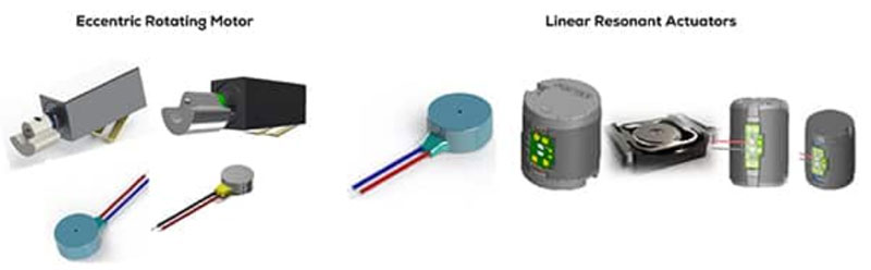
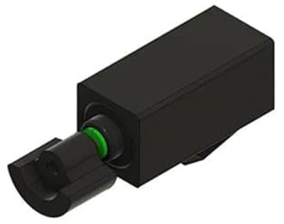
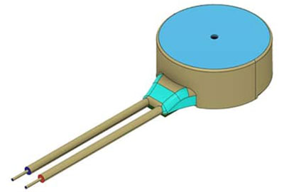
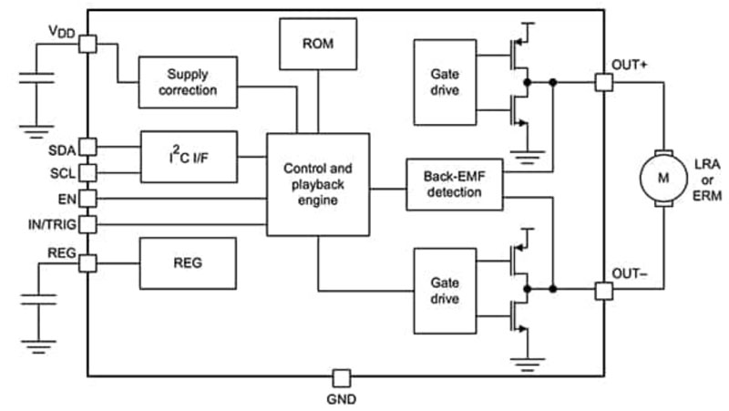
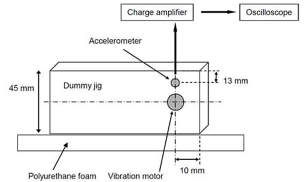
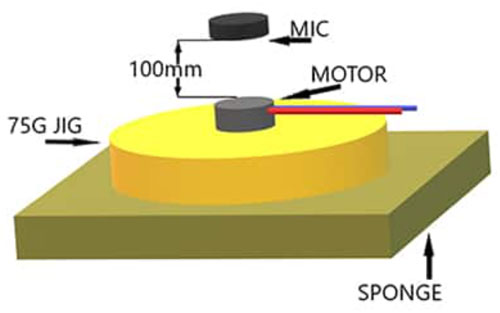
Figure 1: ERM provides strip or coin package, while LRA provides coin, barrel or prism format. (Image source: PUI Audio)
Coin ERM device
For applications such as wearable devices that can benefit from coin ERM devices, designers can use HD-EM0803-LW20-R with a diameter of 8 mm and a thickness of 3 mm from PUI Audio. The specifications of HD-EM0803-LW20-R include:
·Rated speed 12000 (± 3000) revolutions per minute (rpm)
·Terminal resistance 38 Ω (± 50%)
·Input voltage 3 V DC
·Rated current consumption 80 mA
·Operating temperature range - 20 to+60 ° C
For devices that need to work in a more challenging thermal environment, designers can use HD-EM1003-LW15-R instead, with a rated operating temperature of - 30 ° C to+70 ° C. It has the same rated speed and size as HD-EM0803-LW20-R, its terminal resistance is 46 Ω (± 50%), and its rated current consumption is 85 mA. Both coin ERM devices can be driven by positive and negative DC to achieve clockwise or counterclockwise rotation. They consist of 20 mm conductors for flexible electrical connections and generate acoustic noise of up to 50 dBA.
Bar ERM
HD-EM1206-SC-R is 12.4 mm long and 3.8 mm wide. When driven by 3 V DC, the rated speed is 12000 (± 3000) rpm, and the rated operating temperature is - 20 to+60 ° C, which can produce acoustic noise of up to 50 dBA. HD-EM1204-SC-R (Figure 2) can be used for designs requiring lower acoustic noise levels. This model produces a maximum acoustic noise of only 45 dBA. Compared with HD-EM1206-SC-R, it also has a higher rated speed of 13000 (± 3000) rpm and a wider operating temperature range of - 30 ° C to+70 ° C. Both devices have a lower terminal resistance of 30 Ω (± 20%) and a rated current consumption of 90 mA.
Figure 2: HD-EM1204-SC-R ERM is applicable to applications with low acoustic noise level requirements. (Image source: PUI Audio)
LRA device
HD-LA0803-LW10-R LRA device (Fig. 3) with PUI Audio diameter of 8 mm and height of 3.2 mm can be used for designs requiring faster response speed, higher energy efficiency and stronger vibration. Compared with ERM tactile devices, LRA devices have higher accuracy. For example, the resistance range of ERM device is 30 (± 20%) to 46 Ω (± 50%), while the resistance specification of HD-LA0803-LW10-R is 25 Ω (± 15%). HD-LA0803-LW10-R consumes about 180 mW (2 VRMS x 90 mA), while the ERM devices discussed above consume 240 to 270 mW. The operating temperature range of this LRA device is - 20 to+70 ° C.
Figure 3: HD-LA0803-LW10-R LRA is characterized by strong vibration, fast response and high energy efficiency. (Image source: PUI Audio)
system integration
The use of double-sided tape is the preferred assembly method for coin type tactile devices, which can provide the best vibration coupling for the system. The double-sided tape device includes leads that require through hole connection and are manually soldered to the circuit board. Bar, barrel, and prismatic devices are available in two different system integration styles: double-sided tape and spring contacts. When using double-sided tape, these devices include the same manually soldered leads as coin type devices. The vibration coupling function can be combined with the electrical connection by using spring contacts. The spring contact eliminates the need of manual welding, simplifies the assembly and reduces the cost. In addition, the use of spring contacts can also simplify field maintenance.
Driving tactile devices
Discrete drive circuits can be used with LRA and ERM devices. Although the use of drivers made of discrete components can reduce costs, especially the relatively simple design, compared with driver ICs, it may lead to a larger size of the solution and a longer time to market. For applications requiring compact and high-performance solutions, designers can use the DRV2605L of Texas Instruments instead. DRV2605L is a complete closed loop control system that can achieve high-quality touch feedback and can be used to drive ERM and LRA devices (Figure 4). The DRV2605L can use Immersion‘s TouchSense 2200 software, which has more than 100 licensed tactile effects and audio to vibration conversion functions.
Figure 4: DRV2605L IC can drive LRA or ERM tactile devices. (Image source: Texas Instruments)
Vibration test
Since the operation of tactile devices is based on vibration, their structures must be very solid. PUI Audio specifies a test fixture for vibration testing, as shown in Figure 5. The test is realized by an industrial electric vibration test system. It can be programmed for specific vibration test to simulate various working conditions, such as sinusoidal vibration, random vibration and mechanical shock pulse.
Figure 5: Recommended test fixture for vibration testing of tactile devices. (Image source: PUI Audio)
PUI Audio has specified three vibration tests for its tactile devices (see Table 1). After the device is tested and "rested" for four hours, it must meet the specifications of rated speed (for ERM devices) or acceleration (for LRA models), resistance, rated current and noise.
Table 1: Vibration test specifications of tactile devices. (Source: PUI Audio)
In addition to the vibration test, PUI Audio also defines the impact test as follows:
·Acceleration: half sine wave 500 g
·Duration: 2 ms
·Test/face: 3 times/6 faces, 18 impacts in total
The pass/fail criteria are the same as the vibration test.
Measurement of acoustic noise
The acoustic (mechanical) noise level generated by tactile devices is different, and the installation method of tactile devices plays a key role in reducing the noise level as much as possible. PUI Audio recommends using specific test settings to measure the acoustic noise of tactile devices, as shown in Figure 6. The test shall be conducted in a shielded room with an ambient noise of 23 dBA. If the device is installed in a 75 g fixture as expected for the system installation, this test will tell the designer the expected noise level in the application.
Figure 6: Recommended test fixture for measuring acoustic noise of tactile devices. (Image source: PUI Audio)
epilogue
By providing users with touch based feedback, touch sensitive devices can be used to improve HMI performance and help create a high-performance multisensor environment. However, when considering the use of tactile devices, designers need to understand the tradeoff between ERM and LRA technologies, how to effectively drive these two technologies, and how to test to ensure the required system reliability and performance level. As shown above, touch sensitive devices, drivers and test programs are readily available.
|
Disclaimer: This article is transferred from other platforms and does not represent the views and positions of this site. If there is any infringement or objection, please contact us to delete it. thank you! |


 Business consulting

 13823761625
 Mail me