


How to Control Brushless DC Motor
Time:2022-11-17
Views:1474
High power brushless motor must be controlled by PWM, and micro controller is required to provide starting and control functions. Do you know the role of PWM in brushless DC motor control?
When choosing or developing electronic equipment using pulse width modulation (PWM) to drive brushless DC motor, motion control system designers often face challenges. Pay attention to some basic physical phenomena to avoid unexpected performance problems. This paper provides a general guidance for the use of PWM driver with brushless DC motor.
Commutation of Brushless DC Motor
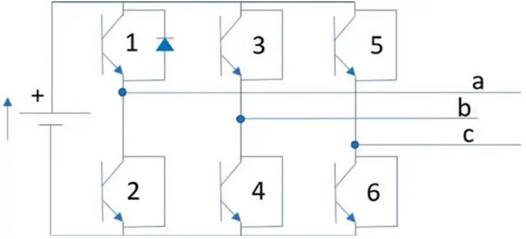
Brushed DC motors use mechanical commutation, while brushless DC motors use electronic commutation. This means that the phase of the motor is energized and de energized according to the position of the rotor relative to the stator. For three-phase brushless DC motors, the driver consists of six electronic switches (usually transistors), commonly referred to as three-phase H-bridge (Figure 1). This configuration allows three bi-directional outputs to energize three phases of the motor.
Figure 1: A three-phase motor H-bridge composed of six transistors is connected to three motor phases.
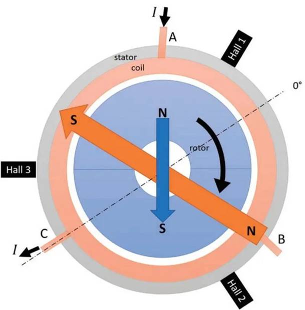
Turn on and off the transistors in a specific order to energize each phase of the motor, so as to ensure that the magnetic field generated by the induction of the stator and rotor magnets maintains the optimal direction (Figure 2).
Figure 2: Cross section diagram of slotless brushless DC motor. The blue area is the rotor with a two pole permanent magnet. The magnetic field generated by the magnet is indicated by a blue arrow. The orange area is three-phase winding. When the current flows from phase A to phase C, a magnetic field will be generated, which is indicated by an orange arrow for simplification. When the two arrows are aligned, the rotor will rotate. The driver changes the phase (rotating the stator magnetic field, orange arrow) to ensure that the stator and rotor magnetic fields are kept at 90 degrees as far as possible (generating the maximum torque).
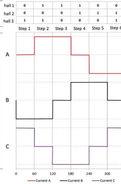
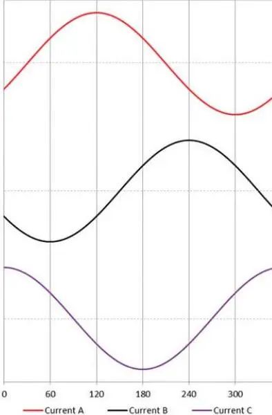
The widely used six step trapezoidal commutation drive can be adopted for the motor (Figure 3), and more advanced vector control, also known as field oriented control (FOC), can be realized through operation, depending on the complexity of the electronic equipment (Figure 4).
Figure 3: Six step commutation phase current and Hall sensor status.
Figure 4: Phase current using FOC amplifier.
PWM Regulation of Brushless DC Motor
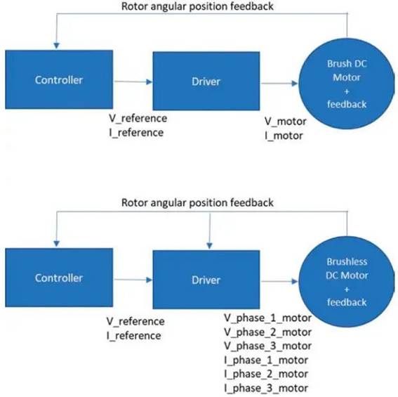
In brushless or brushless DC motors, the operating points (speed and torque) of the application may vary. The role of the amplifier is to change the supply voltage or current, or both, to achieve the desired motion output (Figure 5).
Figure 5: Comparison of motion control architecture between brushless DC motor and brushless DC motor.
There are usually two different ways to change the voltage or current:
·Linear amplifier;
·Chopper amplifier.
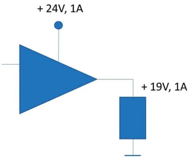
The linear amplifier adjusts the power transmitted to the motor by changing the voltage or current. Power not delivered to the motor is dissipated (Figure 6). Therefore, a large radiator is needed to dissipate power, thus increasing the size of the amplifier and making it more difficult to integrate into the application.
Figure 6: Example of a linear amplifier that supplies power to a motor.
Chopper amplifiers regulate the voltage (and current) by switching the power transistors on and off. Its main advantage is to save power when the transistor is turned off. This helps save battery life for applications, reduces the heat generated by electronic devices, and allows smaller electronic devices to be used. In most cases, the chopper amplifier uses the PWM method.
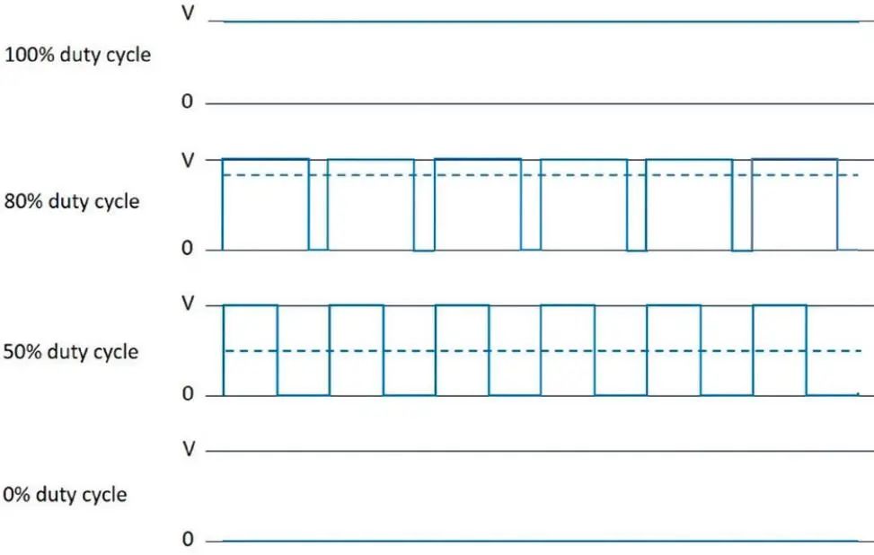
The PWM method includes changing the duty cycle at a fixed frequency (Figure 7) to adjust the voltage or current to the desired target value. Note that one advantage of PWM chopping current over other methods is that the switching frequency is a fixed parameter. This makes it easier for electronics designers to filter electromagnetic noise. When the PWM transistor duty cycle is 100%, the voltage applied to the motor is bus voltage. When the duty cycle of the transistor is 50%, the average voltage applied to the motor is half of the bus voltage. When the transistor duty cycle is 0%, no voltage is applied to the motor.
Figure 7: Different PWM duty cycles. The frequency is the same under all operating conditions, and the average voltage (dotted line) is proportional to the duty cycle.
Inductance Effect of Brushless DC Motor
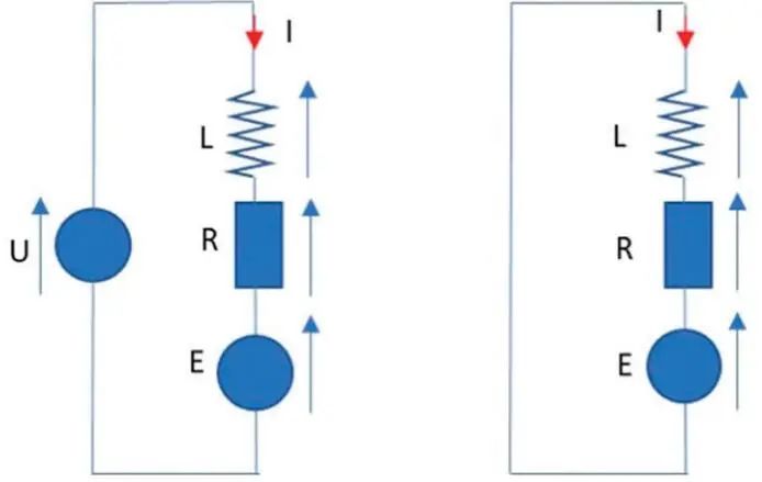
DC motor is characterized by inductance L, resistance R and back EMF E in series. The back EMF is the voltage generated by magnetic induction (Faraday Lenz induction law), which is opposite to the applied voltage and proportional to the motor speed. Figure 8 shows the motor with PWM on and PWM off.
Figure 8: Simplified equivalent circuit diagram of DC motor when PWM is on (left) and off (right). For simplicity, the right side circuit corresponds to a slow decay mode (current recirculation in the motor).
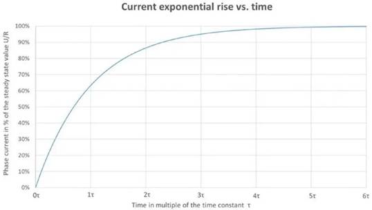
Now, for the sake of simplicity, we do not consider the back EMF. When voltage is applied or cut off to the R L circuit, the inductor will stop the change of current. Applying voltage U to R L circuit, the current will follow the first order exponential rise, and its dynamics depend on the electrical time constant determined by L/R ratio τ (Figure 9). After 5 times of time constant, it will gradually reach the steady value, i.e. 99.7% U/R.
Figure 9: The current in RL circuit increases exponentially.
When the R-L circuit is discharged, the same exponential behavior will be observed. In fact, the brushless DC amplifier has a fairly high PWM frequency, and the current is not easy to achieve steady state. This frequency is usually higher than 50 k H z, so there are enough cycles to properly modulate the current in each commutation step. For a PWM frequency of 50k H z, the cycle time for switching the transistors off and on is equal to 20 μ s。 Considering the six step commutation, a single commutation time of a single pole pair motor running at 40000 r p m (667H z) requires 250 μ s。 In this way, there are at least 250/20=12.5 PWM cycles during one step commutation.
Electrical time constant of brushless DC motor τ It is hundreds of microseconds. Therefore, during each PWM cycle, the current will have time to react. However, the mechanical time constant is in the range of several milliseconds, so the coefficient between the mechanical time constant and the electrical time constant is 10. Therefore, when the voltage is switched at a typical PWM frequency, the motor rotor itself does not have enough time response. A low PWM frequency of several thousand Hz may cause rotor vibration and audible noise. It is recommended to use a spectrum higher than the audible frequency, i.e. at least above 20 kHz.
PWM Limitation of Brushless DC Motor
PWM will cause the current to rise and fall for each cycle. The change between the minimum and maximum current is called the current ripple. High current ripple can cause problems. It is recommended to keep it as low as possible. The average current shall be considered for motor torque. The average current depends on the duty cycle and is independent of the current ripple.
Unlike brushless DC motors, brushless DC motors do not have brushes. High current ripple has no effect on the life itself. The current fluctuation will have a great impact on the motor loss and generate unnecessary heat. Current ripple will produce two types of losses:
Joule loss. The current ripple will increase the root mean square (RMS) current value, which is considered in the joule loss calculation. Ripple will generate additional heat, but will not increase the average current and therefore will not increase torque. Note that it is the square of the RMS current function change.
Iron loss. According to Faraday‘s law of electromagnetic induction, the change of magnetic field in conductive materials will generate voltage, and then generate a current loop called eddy current. Iron loss is proportional to the square of motor speed and the square of motor current. According to the actual measurement, when the current ripple is large, the extra iron loss will be significantly increased. Therefore, it is important to keep the current ripple as low as possible.
Recommendations for minimizing current ripple
We can make some suggestions to minimize ripple:
Reduce or adjust the supply voltage. The current ripple is proportional to the supply voltage. High voltage helps to reach the extreme operating point requiring high speed or higher power. However, if the application does not require high speed or high power, a lower supply voltage will help reduce current ripple. At the same load point, operating at a lower voltage will also increase the duty cycle, which will further reduce the current ripple. Be sure to keep the PWM duty cycle within 50% as far as possible, which is the worst case.
Increase the PWM frequency. The higher the frequency, the shorter the PWM cycle; Therefore, the current rise time is shorter. It is recommended that the PWM frequency of brushless DC motor should not be less than 50 kHz. 80 kHz or higher PWM frequency is more suitable for motors with very small electrical time constant.
Increase inductance. The inductance of brushless DC motor is very small. It is a good idea to add external inductors, because they can slow down the rise and fall of the current, thereby reducing the current ripple. In addition, a specified inductance value is given for a PWM frequency of 1 k Hz. As the motor inductance changes with PWM frequency, the inductance may be reduced to 70% of the specified value at a typical PWM frequency of 50 kHz.
The best value of inductance is usually determined by experiments. Additional inductance is required, as shown in Figure 10. Although this solution can solve the current ripple problem, it may not be easy to integrate additional inductors, especially when space is limited. Therefore, it is usually a wise choice to explore the other two options first.
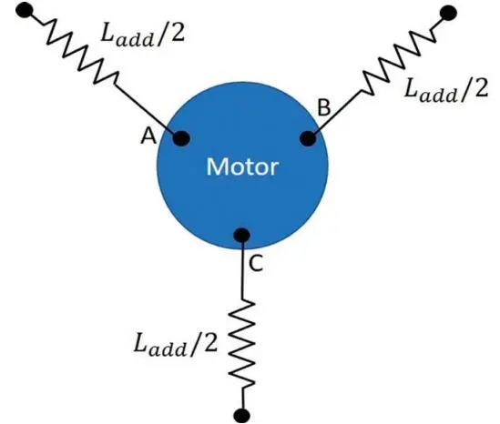
Figure 10: Brushless motor with additional line inductance.
PWM has many advantages and is the most widely used solution in brushless DC motor. Setting appropriate PWM voltage and using higher PWM frequency will help reduce ripple and avoid using additional inductance. Thanks to the low cost of electronic components, it is a simple solution to adopt high PWM frequency.
When it comes to the size and weight of electronic equipment (such as portable equipment of embedded electronic equipment), or when battery life is a key indicator (additional energy consumed by joule loss of additional inductance internal resistance), electrical designers should consider these parameters when developing motion control systems.
Key concepts:
■ Review PWM regulation of brushless DC motor.
■ Understand the limits of brushless DC motor PWM.
Think about it:
Are you addressing the challenges of selecting or developing electronic devices that use PWM to drive brushless DC motors?
|
Disclaimer: This article is transferred from other platforms and does not represent the views and positions of this site. If there is any infringement or objection, please contact us to delete it. thank you! |


 Business consulting

 13823761625
 Mail me