


Field oriented control (FOC) for three-phase motors
Time:2022-12-11
Views:1365
Electric motors play a vital role in today‘s industry and daily life. Brushless DC (BLDC) and AC motors are used in various applications, from household appliances to automobiles and heavy industrial robots, because they are more energy efficient and customizable. AC and BLDC motors are preferred in many applications because of their few disadvantages, such as the cost of microcontrollers and complex control algorithms.
This series of blogs will discuss some different motor control schemes, starting with BLDC or field oriented control (FOC) of AC motors.
FOC is one of the most effective ways to drive electric motors. The main objective of FOC is to maintain orthogonal stator and rotor magnetic fields to produce maximum torque. One method is to continuously monitor the three time-varying phase currents and modulate each applied phase voltage to achieve the correct time-varying stator magnetic field direction. However, this is easier said than done, and it is also difficult in practice due to the increase of hardware/software requirements.
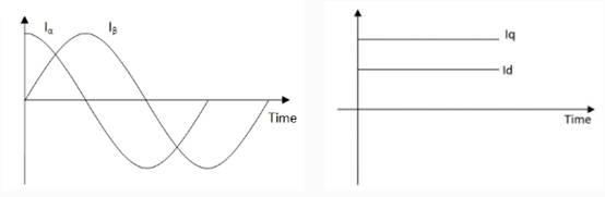
In field oriented control, time-varying currents are still monitored and projected onto a stationary reference frame, where they are decomposed into torque (q-axis) and field flux (d-axis) components. This is done mathematically through Clarke transformation and Park transformation, which helps to directly control torque in a time invariant reference coordinate system, reducing the complexity of control and bandwidth requirements.
Figure 1: Using Clark transform (I α And I β) Project three-phase current, and then project to linear d, q rotation reference coordinate system through Parker transformation
Then, the d-q axis component of the command is converted back to the 3-phase time-varying system to correctly modulate the 3-phase current through the PWM control of the inverter switch.
However, the magnetic field angle of the rotor must be known to maintain the orthogonal stator and rotor magnetic fields. This can be achieved through the position feedback of the encoder or resolver (with sensors), or the phase current can be measured through the back EMF/flux observer software to estimate the rotor angle (without sensors).
Encoders are generally divided into two categories: incremental and absolute. Incremental encoder can measure relative angular position and direction of rotation, but it cannot provide absolute position information at zero speed. For example, for an incremental quadrature encoder, two A/B pulse signals of the quadrature phase represent relative angular motion (for example, 1000 pulses per revolution), and sometimes an additional Z index signal is provided to provide a reference point. The polarity of the relative phase of the A/B signal (for example, A lagging B or B lagging A) indicates the direction of rotation. Absolute encoders provide true angular position through various digital codes. However, due to the increase in the number of signals and bandwidth requirements, they often require the communication bus to send signals to the controller (for example, 16 bit position coding).
Phase current detection
Whether sensor or sensorless implementation mode is selected for FOC, the phase current must be accurately measured to maintain accurate torque control. The most common method to measure the phase current is to use a shunt resistor in the inverter stage to detect the low side between the source and the ground of each low side MOSFET. Due to the lower common mode voltage of the shunt, low-cost current detection amplifiers can be used. High side (series) phase current detection usually requires expensive professional CMRR or isolated amplifier circuit with high common mode rejection ratio to reduce common mode voltage error, because common mode voltage fluctuates roughly between DC input voltage and ground at PWM frequency.
Ideally, the currents of all three phases are measured at the same time, but it is possible to reduce the number of shunt resistors, thus reducing the system cost and power loss, but increasing the current detection bandwidth and software complexity. The double shunt architecture relies on Kirchhoff‘s current law to calculate the unmeasured current from the two measured currents (for example, the current flowing into U and V phases is equal to the current flowing out of W phase). The single shunt architecture needs to know the inverter switch status to correlate the measured current with the actual phase current.
In general, the measurement accuracy used to determine all phase currents decreases as the number of shunt resistors decreases (from 3 to 1). Therefore, a faster measuring circuit is required, and the total system delay becomes a more important factor. In addition, the software complexity will also increase in tracking the correct time of detection and determining the correlation between the measured current and the actual phase current, which is most obvious in the single shunt architecture.
Figures 2 and 3 below illustrate the sensorless and sensorless FOC motor control systems.
With sensor FOC
Figure 2: Block Diagram of Sensorless FOC Motor Control System
Figure 2 shows the signals required for a sensored FOC implementation using a quadrature encoder. Feedback requires at least 1-3 current detection inputs (depending on the shunt architecture) to ADC and 3 GPIO pins for quadrature A/B/Z signals. The encoder must also be powered.
Sensorless FOC
Figure 3: Sensorless FOC motor control system block diagram
Figure 3 shows the signals required to implement a sensorless FOC. According to the shunt architecture, ADC requires at least one to three current detection inputs to provide feedback.
The motor development kit STR-1KW-MDK-GEVK and STR-MDK-GEVK 4KW-65SPM31-GEVK are two comprehensive motor control schemes. They use high-power modules to drive the motor with sensor and sensorless FOC control.
Protection function
Overcurrent protection (OCP)
For FOC, since the low side current detection has been used for control, these same signals can also be used for OCP. However, as previously mentioned, low side current detection can only detect faults in inverter stage and motor. Additional high side bus current detection circuits can be implemented to prevent other faults downstream of the power supply.
Hardware, software, or both can implement OCP. Generally, hardware based OCP will provide faster response, but software based OCP is more flexible. ADC‘s full range current measurement range limits the maximum trigger point of the software based OCP. The combined implementation of hardware/software can be used to implement latch OCP to quickly mitigate catastrophic hard faults, while software based OCP can control dynamic events, such as periodic phase current limitation.
Overvoltage protection (OVP)
In certain applications, such as regenerative braking may cause excessive voltage on the DC bus, it may be necessary to achieve HW OVP through diode clamping or crowbar circuits. Software based OVP can also be realized by monitoring the DC bus, and protecting the motor from potential damage voltage higher than the rated voltage of the motor by disabling the inverter output.
Over temperature protection (OTP)
Monitoring inverter MOSFET and/or circuit board temperature is usually a good idea for all control methods, especially when the system is subjected to different ambient temperatures or the cooling system fails. For example, the PWM duty cycle limit can be dynamically reduced as the temperature increases, and thermal monitoring can also help determine device degradation over time.
MOSFET gate driver
The selection of gate driver of inverter MOSFET is very important for any motor control system, and it should be clearly selected according to the system requirements. Improper selection of gate driver may lead to significant performance degradation, even catastrophic system failure.
Onsemi has a variety of single-phase HS-LS MOSFET gate drivers, such as NCP51530 and FAN73933, which can be used for each inverter phase (3 in total). However, for 3-phase motor control, special integrated 3-phase gate drivers can also be used, including FAN7388, FAN73896 and FAN7888.
Generally speaking, the original performance of three single-phase gate drivers is better than that of the integrated three-phase scheme, because the coupling with each phase is closer. However, integrated three-phase drivers usually also realize the common auxiliary functions in motor control applications, reducing the complexity of hardware, the number of components and the size of the circuit board.
In addition, some gate drivers have the functions of automatic complementary gate drive output and dead time insertion, which allows a single PWM output (the required PWM controller signals are reduced from 6 to 3) to control each inverter phase. Please note that this function is not suitable for some PWM schemes.
Combined with basic protection technology, FOC can become one of the most effective methods to drive motor, and also a good method to improve motor control and accuracy in various applications.
|
Disclaimer: This article is transferred from other platforms and does not represent the views and positions of this site. If there is any infringement or objection, please contact us to delete it. thank you! |


 Business consulting

 13823761625
 Mail me