


High brightness LED driving power supply without electrolytic capacitor
Time:2022-12-14
Views:1356
This scheme takes prolonging the service life of the circuit as the theme, combines the advantages of switching power supply and linear power supply, and takes full advantage of their respective advantages. Because switching power supply has the characteristics of high efficiency energy conversion and linear power supply has the characteristics of no output ripple, this design scheme takes full advantage of their respective advantages to replace electrolytic capacitor filtering, effectively solving the problem of short life of existing LED. This LED driver circuit does not have large capacity electrolytic capacitors. Small capacitors can use long-life film capacitors and other capacitive components, making it have the characteristics of long life, high efficiency, low ripple current, and high security and stability.

1. Preface
LED (Light Emitting Diode) is a new generation of green lighting source, which has many advantages such as energy saving, environmental protection, high brightness, long life, etc. It is not only a new favorite of lighting sources, but also closely related to people‘s lives. Therefore, the key to LED lighting quality and overall performance is to develop a long-life driving power supply and build a high efficiency, low cost, high power factor, which is also the need for LED lighting technology development. According to incomplete statistics, the service life of existing incandescent bulbs is about 40 times less than that of LED lamps. Because LED is not only a DC current driver, but also a photoelectric converter, with the function of photoelectric conversion. Its function is mainly to convert electric energy into light energy by flowing current, so its advantage is that it has higher energy saving efficiency and working life than ordinary light sources. However, large capacity electrolytic capacitors are generally used in the rectification circuit and filter circuit of LED drive power supply. The service life of the electrolytic capacitor is generally l05 ℃/2000h, which means that when the temperature around the capacitor rises to 105 ℃, its service life is only 84 days. Even if it works in an environment with a temperature of 85 ℃, its service life is only 332 days. Therefore, the electrolytic capacitor is the main reason that hinders the life of the LED drive circuit. In order to improve the life of the driving power supply, it is necessary to remove the electrolytic capacitor. In this paper, a high brightness LED driving power supply without electrolytic capacitor is proposed.
2. Operating principle of LED drive circuit
The circuit topology adopts flyback topology circuit, uses PWM to control the switching frequency, so that it can output constant current and voltage to drive LED lights. It mainly includes: front protection circuit, filter circuit, rectifier circuit, RCD clamping circuit, synchronous rectifier circuit, power conversion circuit, output filter circuit, feedback circuit, control circuit, etc.
In order to make the circuit less affected by electromagnetic interference, the EMI filter circuit is connected to the front protection circuit, through which the high-order harmonics in the circuit and the surge in the circuit are filtered.
On the input rectifier part, it is composed of bridge rectifier circuit and π - type filter circuit respectively. Because the diode has the characteristics of unidirectional conduction, the bridge rectifier circuit can convert AC to unidirectional DC, and then output stable DC voltage under the action of π - type filter circuit.
Then the output is adjusted and controlled by the control circuit to reach the design value. After the output filter circuit, the output ripple is reduced to DC, and the DC is output to LED for use.
3. Specific design of LED
3.1 Design of input circuit
The indicators of this design circuit are: input AC voltage Vin: 90-264 VAC/50-60Hz; Output voltage Vo: 27VDC; Output current Io: 0.68A
As shown in Figure 2, the input circuit includes safety device, EMI noise filtering device, bridge rectifier circuit and π type filtering circuit.
As shown in Figure 2, in order to reduce electromagnetic interference in 1MHz frequency band, EMI noise filtering circuit is composed of capacitors C1, C2 and inductors L1 and L2. The safety device is composed of fuse and ZNR. When the peak current of hazardous circuit is generated, the fuse will quickly cut off the circuit to protect the load; ZNR is a surge absorber. When static electricity and surge occur at the input end of the drive circuit, it will become very high impedance, so it can protect the following circuits. The bridge rectifier filter circuit is used to convert alternating current into direct current, and the following π - type filter is used to filter the ripple of voltage and current in the circuit.
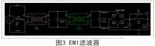
3.1.1 Design of EMI filter
The EMI filtering circuit diagram is shown in Figure 3. The EMI filtering circuit consists of differential mode capacitors CX1 and CX2 in front of the rectifier bridge, which are mainly used to attenuate differential mode interference, and their values are generally large.
In order to reduce differential mode interference, a π type differential mode filter composed of C1, C2 and L1 is added behind the rectifier bridge.
The differential mode capacitor in the EMI filter circuit adopts the X safety gauge capacitor, the safety level is X2, and its withstand voltage value is 2500V, in which CX1=0.47uF, CX2=0.01uF. The common mode inductance LX1 is 7mH and LX2 is 1mH The C1 and C2 filter capacitors of the π type filter circuit behind the rectifier bridge are 450V withstand film capacitors with a capacitance value of 0.22uF; The differential mode inductance L1 is 1mH
|
Disclaimer: This article is transferred from other platforms and does not represent the views and positions of this site. If there is any infringement or objection, please contact us to delete it. thank you! |


 Business consulting

 13823761625
 Mail me