


How to make LED bulb dimmable
Time:2023-01-20
Views:1278
Over the years, manufacturers have continuously introduced LED lamps to the market, with the ultimate goal of replacing incandescent lamps and compact fluorescent lamps (CFL). These bulb designs have evolved from very simple non-dimmable schemes to advanced but expensive dimmable schemes, and then to more cost-effective dimmable schemes.
Many LED lamps claim to be dimmable, but in fact, the performance of many LED lamps is not very ideal, and the performance varies due to the different dimmers and circuit loads used. Sometimes, after the LED lamp is installed in the room with a dimmer, the LED lamp will flash and cannot adjust the brightness evenly.
These defects are due to the fact that most of the dimmers used in the United States at this stage are based on the two-way thyristor (TRIAC) two-wire leading edge phase-cutting circuits, which were developed in the 1960s and are suitable for resistive incandescent lamps. TRIAC is a bidirectional semiconductor power switch, triggered by a pulse generated by a variable timing circuit, and maintains continuity when the conduction current is higher than the holding current. There are many types of dimmer circuits, which use different devices with different characteristics, as well as different control circuits and filter elements.
The driver circuit of LED lamp converts AC input power into low-voltage DC power and maintains a stable current to drive high-brightness LED load to obtain constant light output. If you want to adjust the basic LED driver circuit through the dimmer based on the bidirectional thyristor, you must add some additional components to achieve stable dimmer operation, and adjust the output current according to the dimmer phase angle.
Due to the large difference of dimmers, the performance of the connected LED dimmer circuit is also different. Because there is no clear standard to divide the performance of LED bulbs with dimmers, this problem becomes more complex. At most, some bulb manufacturers will provide dimmer lists, listing dimmers that they think are compatible with their products.
With the support of the United States of Energy (DoE), the National Electrical Manufacturers Association (NEMA) is working to develop dimming standards applicable to LED lamps driven by phase-cutting dimmers, including test procedures and indicators to determine whether acceptable performance is achieved. It is hoped that this standard will eventually help clean up those products on the market that claim to be dimmable, but whose performance is far from reaching the soft and stable incandescent dimming expected by end users.
Most of the driving circuits used by LED bulbs include buck, boost or flyback converters. In all cases, acceptable dimming performance can be achieved by modifying the basic circuit without increasing the cost and complexity of the device. In this way, the performance of dimmable drivers can be improved to meet the cost saving requirements of the consumer lighting market.
The compatibility problem is how the TRIAC dimmer circuit interacts with the LED driver input circuit.
The example circuit of single-stage LED driver (Figure 2) replaces the resistive load representing incandescent lamp in Figure 1. Although this circuit simulates resistive load due to its high power factor in stable operation, its front end also includes capacitors necessary for EMI filtering. In addition, LED bulbs consume less power than 25% of the equivalent incandescent lamps. As a result, before TRIAC is triggered, the dimmer mainly bears capacitive load in the half cycle of AC line.
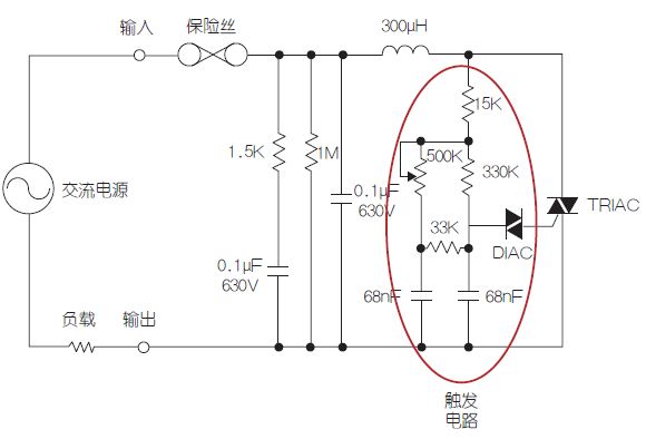
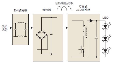
Figure 1: Typical dimmer schematic diagram
Figure 2: Basic LED driver circuit diagram
If the bidirectional trigger circuit shown in Figure 1 wants to operate according to the design goal, it also needs a resistive path to the neutral point. If it is changed to capacitive load, this circuit will not operate normally, and will cause unstable triggering when the cycle is switched, which is manifested by the continuous flashing of the output light. The EMI filter in the dimmer and LED driver will also cause ringing oscillation due to the high dv/dt at TRIAC startup.
When the oscillation amplitude reaches a certain degree, it will cause the current to fall below the "holding current", thus making the TRIAC closed, but it is impossible to maintain the TRIAC continuity before the next line zero crossing. In this case, TRIAC will be turned on and off several times in a single line half cycle due to the trigger circuit re-triggering. In addition to causing stress on the components and possibly damaging the dimmer or LED driver, this will cause serious flicker and unpleasant noise.
Assuming that it is not an ideal solution to replace the dimmer with the dimmer applicable to the LED lamp, the above problems can be solved by modifying the LED driver, so as to realize the combination of the LED driver and the standard dimmer.

Figure 3: Schematic diagram of dimmable LED drive.
The example circuit (Figure 3) is a single-stage LED flyback converter, and the same technology can also be used for voltage rise/fall or adaptive voltage reduction converter. First of all, the input capacitance must be kept at the minimum value when designing the input filter, which also helps to achieve the best power factor.
The next step is to introduce the active attenuator and passive bleeder circuits. The attenuation circuit will limit the impulse current when TRIAC is triggered, thus greatly suppressing the ringing, so that TRIAC remains on. After a short time delay, the attenuation resistance is bypassed by a small MOSFET to prevent power loss during the remaining conduction period. In order to minimize the cost of low-power drivers, bypass MOSFETs and their related drive circuits can be ignored, but this will lead to heat dissipation of resistors and related efficiency losses.
Passive bleeder circuits can be used instead of active bleeders used in some dimming solutions. The series RC network conducts the current from the trigger point, and the time is enough for the switch converter to start drawing the current, which helps to ensure that the current will not fall below the holding current during this period. As the main resistive load connected to the DC bus, the flyback or step-down converter operating with constant on-time can maintain the on-state of the dimmer TRIAC before the next line zero-crossing. The converter needs to draw enough current to maintain above the TRIAC holding current. Single-stage PFC flyback or boost converter can usually achieve this goal.
The circuit described here uses IRS2983 controller IC, which operates in voltage mode. The DC voltage level at the COMP input determines the turn-on time of the switching cycle. Because the controller IC is often used with the primary side adjustment to maintain a constant output power, it is necessary to add a Zener diode on this input to clamp the COMP voltage. This limits the maximum turn-on time, so that when the DC bus voltage drops during dimming, the turn-on time cannot be increased to compensate.
As a result, the output current will decrease as the dimmer setting decreases and the DC bus voltage decreases. In this way, the light brightness can be adjusted to less than 20% by adjusting the dimmer control without using more complex circuits to detect the dimmer phase angle or adjust the output. At the same time, the controller VCC power supply must be released during dimming off to ensure that the IC operates only for the required time. For this purpose, a high-voltage diode is used to connect the VCC and the DC bus.
Active attenuator and passive bleeder circuits can also be used with buck converter, but the result depends on LED voltage. Because the converter cannot draw current when the line voltage is lower than the output voltage, the operating range of phase dimming will be limited. For this reason, the LED voltage should be kept low, but it should not be too low, otherwise the circuit will become invalid, and excessive inductor needs to be used. For 120VAC system with reasonable adjustment range, LED voltage is preferably 20V~40V. CCM buck LED controller IC (such as IRS2980) can maintain the average current regulation of LED lamp while the unsmooth bus voltage is always higher than the total output voltage of LED.
These simple techniques introduced in this paper can make most TRIAC-based dimmers achieve smooth dimming effect without flicker when used with the LED converter described.
|
Disclaimer: This article is transferred from other platforms and does not represent the views and positions of this site. If there is any infringement or objection, please contact us to delete it. thank you! |


 Business consulting

 13823761625
 Mail me