Design of non-flashing LED lamp drive scheme
Time:2023-01-26
Views:1267
The traditional halogen cup lamp uses electronic transformer and AC input, so the current LED lamp products on the market can directly replace the traditional halogen cup lamp by installing a rectification circuit inside. Although the traditional electronic transformer is cheap, its relative quality is mixed. Because the electronic transformer is in fact controlled by half-bridge rectifier and its output varies with the load impedance, the circuit stability is poor. When the circuit matching is wrong, LED-MR16 lamps are prone to flicker or not light.
In the current reference design of 3-5WLED-MR16 lamp, three 1W LED series outputs are mostly used, and the input voltage is AC 12V ± 10%. If the LED drive circuit architecture adopts DC step-down mode, it can effectively output under normal power supply, but due to the stability of the electronic transformer, the input voltage of the LED drive circuit may be higher or lower than the output voltage, resulting in the DC step-down drive circuit can not work, and the LED current can not be continuously connected, which is the main cause of LED MR16 flashing.
Solution:
• The circuit structure adopts a step-down converter
• Wide drive voltage range and input protection
In order to solve the above flicker problem, it is a better choice for LED driver circuit architecture to adopt a voltage converter. The input voltage higher or lower than the output voltage can be used to drive the LED series circuit. The efficiency of the voltage up and down conversion circuit can reach more than 85%, and the change of the input voltage can be suppressed in the discontinuous operation mode to provide excellent line voltage regulation.
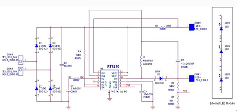
The new RT8450 can be specially designed in the driving application of MR16 LED lamp. Its internal circuit design architecture can easily realize the voltage rise and fall circuit, as shown in Figure 1.


Figure 1: The driving circuit of LED-MR16 lamp is realized by using RT8450 voltage rise and fall architecture.
In addition, the RT8450 adopts a very small WDFN package and has a 4.5-40V input voltage range, which makes the drive circuit of the RT8450 provide a wide range of drive voltage and input protection. The working temperature of RT8450 is up to 125 ℃, which can work safely in the high temperature environment of MR16 lamps. Its 500kHz switching frequency allows the drive circuit to use small size inductors and capacitors. In addition, the voltage regulator circuit architecture can reduce the input filter capacitance value, so that the drive circuit can be placed in the MR16 lamp, as shown in Figure 2.


Figure 2: Driver circuit board based on 5WMR16LED and RT8450
Combining the above application circuit with the common electronic transformer on the market, the RT8450 does not flicker under any load condition. As shown in Figure 3, even though the input voltage of the electronic transformer changes greatly due to poor load conditions, the LED of the LED-MR16 lamp with the RT8450 voltage rise and fall circuit still maintains the characteristics of constant current and will not flicker at all. The switching frequency of RT8450 is about 500kHz, and the input 68uF capacitor can be used for the voltage rise and fall circuit. In this example, the total converter efficiency (LED power divided by power from VBAT) can reach 85%. RT8450 adopts peak current detection and average current control mode method to ensure 5% LED current accuracy.


Figure 3: Channel 1 is the AC output voltage of the electronic transformer, channel 2 is the input voltage after rectification and filtering, channel 3 is the AC input voltage, and channel 4 is the LED output current.
In addition, the RT8450 voltage rise and fall architecture has the feature that the LED drive circuit is not affected by the input voltage change, and can support the front circuit to realize the three-terminal bidirectional silicon controlled rectifier (TRIAC) dimming scheme, because this chip can control the RT8450 linear brightness modulation pin after converting the TRIAC chopped wave into a PWM signal, and can control the brightness change of the overall lighting scheme without flickering.
|
Disclaimer: This article is transferred from other platforms and does not represent the views and positions of this site. If there is any infringement or objection, please contact us to delete it. thank you! |


