


Introduction to digital audio interfaces such as I2S, PCM and PDM
Time:2023-02-05
Views:1289
summary
Digital Audio Interfaces (DAI), as the name implies, refers to the way of transmitting digital audio signals at the board level or between boards. Compared with analog interface, digital audio interface has stronger anti-interference ability and simple hardware design. DAI is more and more widely used in audio circuit design. Figure 1 and Figure 2 compare the difference between traditional audio signal and digital audio signal chain.
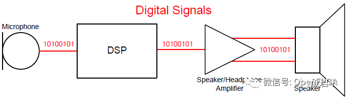
In the traditional audio circuit (Figure 1), there are microphones, preamplifiers, analog-to-digital converter ADC, digital-to-analog converter DAC, output amplifiers, and speakers, which are connected by analog signals. With the development of technology and the consideration of performance, analog circuits are gradually pushed to both ends of the link (integrated into the equipment), and more digital interface forms will appear between integrated circuits in the signal chain. DSP is usually digital interface; Transducers (ie. Mic&Speaker) and amplifiers generally only have analog interfaces, but now they are gradually integrating digital interface functions. At present, integrated circuit designers are integrating ADC, DAC and modulator in the transducer into one end of the signal chain, so that there is no need to walk any analog audio signal on the PCB, and the number of devices in the signal chain is reduced. Figure 2 shows an example of a complete digital audio interface.
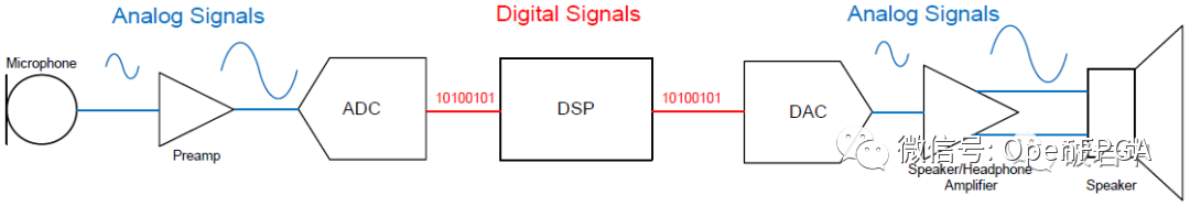
Traditional audio signal link
Digital audio signal link
The transmission standards of digital audio signals, such as I2S, PCM (Pulse Code Modulation) and PDM (Pulse Density Modulation), are mainly used for the transmission of audio signals between chips on the same circuit board; Intel HDA (Intel High Definition Audio) is used for PC audio subsystem (sound card) applications; S/PDIF and Ethernet AVB are mainly used for long-distance between boards and occasions requiring cable connection.
This paper mainly introduces digital audio interfaces such as I2S, PCM and PDM, which are commonly used in on-board interface.
Definition of abbreviations
CAS: channel signaling, voice and signaling transmitted in the same channel
CCS: common signaling, voice and signaling are transmitted separately
ASLA - Advanced Sound Linux Architecture
OSS - previous Linux audio architecture, replaced by ASLA and compatible
Codec - Coder/Decoder
I2S/PCM/AC97 - Audio communication protocol/interface/bus between Codec and CPU
DAI - Digital Audio Interface is actually I2S/PCM/AC97/PDM/TDM, which realizes the communication of audio data between CPU and Codec
Mixer - Mixer, which mixes several audio analog signals from different channels into one analog signal
Mute - Mute, shield signal channel
PCM - Pulse Code Modulation is a technology that converts audio analog signals into digital signals, which is different from PCM audio communication protocol
Sampling frequency - ADC frequency, number of samples per second, typical value is 44.1KHZ
Quantization accuracy - for example, 24bit, is to divide the audio analog signal equally according to the 24th power of 2
SSI - Serial Sound Interface
DAPM - Dynamic Audio Power Management
Codec - Audio codec Codec is responsible for processing audio information, including ADC, DAC, Mixer, DSP, I/O, volume control and other audio-related functions. Codec communicates with the processor through I2C bus and digital audio interface DAI.
I2S interface
1. Introduction to I2S
The full name of I2S is Inter-IC Sound, Integrated Interchip Sound, or IIS for short. It is a digital audio transmission standard defined by Philips in 1986 (revised in 1996). It is used for the transmission of digital audio data between internal devices of the system, such as codec CODEC, DSP, digital input/output interface, ADC, DAC and digital filter. Except that they are all defined by Philips, I2S and I2C have no relationship.
I2S is a relatively simple digital interface protocol without address or device selection mechanism. On the I2S bus, only one master device and one sending device can exist at the same time. The master device can be a transmitting device, a receiving device, or other control devices that coordinate the transmitting device and the receiving device. In the I2S system, the equipment providing clock (SCK and WS) is the main equipment. Figure 3 is a common I2S system block diagram. In high-end applications, CODEC is often used as the main control device of I2S to accurately control the data flow of I2S.
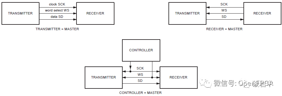

I2S system communication configuration block diagram
IIS Features
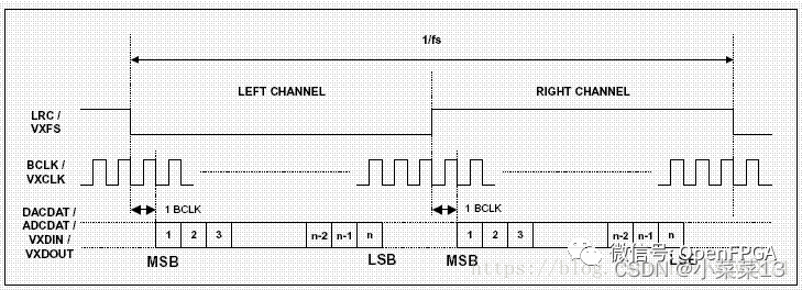
1. Pass high first and then low
2. MSB of data delays 1 BCLK from the edge of LRCLK
3. There are mainly three clocks
Master clock MCLK
The system clock, generally 12.288MHz, 18.432MHz, etc., is 256 times or 384 times the bit clock (Bclk)
Bit clock BCLK (also known as serial) transmits the clock cycle of one bit of data
Frame clock LRCLK low level left channel high level right channel
4. Serial SDDATA audio data represented by binary complement
4. Serial SDDATA audio data represented by binary complement
5. Other methods
The MSB of left-aligned data is rarely used when the first BCLK rises from the edge of LRCLK
The LSB of right-aligned data is on the left. The rising edge of LRCLK sony uses this format
6. Voltage (TTL) output VL<0.4V VH>2.4V input voltage VIL=0.8V VIH=2.0V
Compared with PCM, IIS is more suitable for stereo systems for music transmission.
In the ADC/DAC system with I2S/PCM interface, in addition to BCLK and FS (LRCLK), CODEC often requires the controller to provide MCLK (Master Clock), which is based on Delta-Sigma( ΔΣ) The architecture design requirements of. The clock frequency of MCLK is generally 256 * FS. Refer to the specific device manual for details.
IIS is only a branch of PCM, and the interface definition is the same
They have four sets of signals: bit clock signal, synchronization signal, data input and data output.
PCM generally transmits mono sound and stereo sound, and the sampling frequency is generally 8KHz.
IIS generally transmits stereo sound and has one more line than PCM. The data format is PCM. The coding of one sampling point of the left/right channel is generally 16 bits (quantization depth), and the sum of the two channels is 32 bits.
I2S can only transmit data of 2 channels, and PCM can transmit up to 32 channels of data in a multiple frame.
AC97
AC97 (Audio Codec 1997) is a specification jointly proposed by Intel, Creative Labs, NS, Analog Device and Yamaha, five PC manufacturers led by Intel. Unlike PCM and IIS, AC ‘97 is not only a data format, but also an internal architecture specification for audio coding. It also has control functions. AC ‘97 uses AC-Link to connect with external codecs. The AC-Link interface includes bit clock (BITCLK), synchronous signal correction (SYNC) and data queues from encoding to processor and decoding from processor (SDATDIN and SDATOUT). The AC‘97 data frame starts with SYNC pulse, including 12 20-bit time periods (time periods are different target services defined in the standard) and 16-bit "tag" periods, totaling 256 data sequences. For example, time periods "1" and "2" are used to access the encoded control register, while time periods "3" and "4" load the left and right audio channels respectively. The "tag" segment indicates which of the other segments contains valid data. Dividing the frame into time segments makes it possible to transmit control signals and audio data to 9 audio channels or convert them into other data streams only through 4 lines. Compared with the IIS scheme with separate control interface, AC ‘97 significantly reduces the overall number of pins. Generally speaking, the AC‘97 codec adopts TQFP48 package.
PDM (pulse density modulation) [generally used for digital mic]
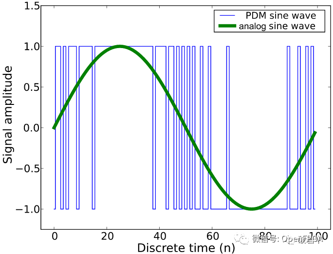
PDM (Pulse Density Modulation) is a modulation method that uses digital signals to represent analog signals. As the same method of converting analog quantity to digital quantity, PCM uses equal interval sampling method to express the amplitude of analog component of each sampling as N-bit digital component (N=quantization depth), so the result of each sampling in PCM mode is N-bit word length data. The PDM uses a clock sampling and modulating analog component that is much higher than the PCM sampling rate, with only 1 bit output, either 0 or 1. Therefore, digital audio represented by PDM is also called Oversampled 1-bit Audio. Compared with a series of 0 and 1 in PDM, the quantitative results of PCM are more intuitive and simple.
At the application receiver using PDM mode as the analog-to-digital conversion method, it is necessary to use the decimation filter to convert the dense density components represented by 0 and 1 into amplitude components, while the PCM mode is already the amplitude-related digital components. Figure 20 shows the sine wave digitized by PDM.
The logic of PCM mode is simpler, but it requires three signal lines: data clock, sampling clock and data signal; The logic of PDM mode is relatively complex, but it only needs two signal lines, real-time clock and data. PDM has a wide application prospect in places with strict space restrictions, such as mobile phones and tablets. In the field of digital microphone, the most widely used is the PDM interface, followed by the I2S interface. Audio signals in PDM format can be routed near circuits with strong noise interference, such as LCD screens (which means that digital signals have stronger anti-interference ability than analog signals, and PCM also has this advantage).
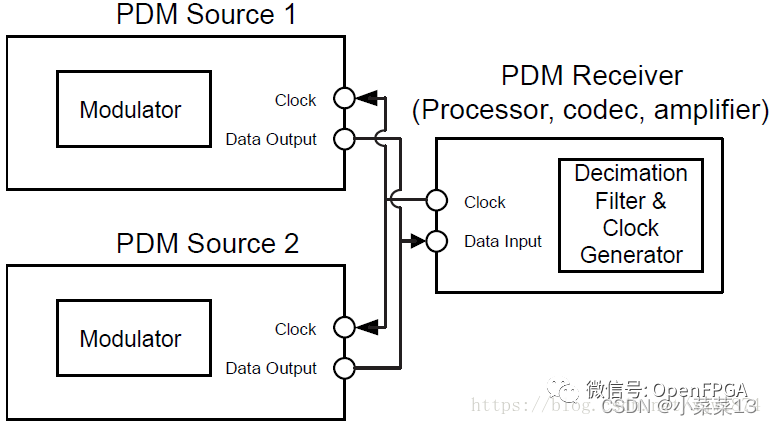
Through PDM interface mode, only two signal lines are needed to transmit dual-channel data. As shown in Figure 21, the connection between the sending equipment of two PDM interfaces and the same receiving equipment is illustrated. For example, the Source 1/2 is used as the microphone of left and right channels respectively. In this way, the collected dual-channel data can be transmitted to the receiving equipment. The master device (as the receiving device in this example) provides the clock for the two slave devices, and triggers the selection of Source 1/2 as the data input at the rising and falling edges of the clock respectively.
Inside the PDM output microphone, a small ADC IC (modulator) can be found, which is used to convert the analog signal output by the MEMS sensor into the PDM signal stream. The low frequency spectrum of the signal generated by this audio converter technology is close to the required audio signal, while the frequency of the high frequency parasitic part rises rapidly with the increase of frequency above a certain inflection point frequency, basically falling outside the range of audio frequency required for the final product. For each sampling point, 1 bit can be used to record, that is, only "0" representing "No" and "1" representing "Yes" can be used to record the level value of this sampling point. In the process of DSD coding, the way to quantify the signal is completely different from PCM. The specific principles are as follows: First Δ Imagine the concept of modulation. Unlike PCM, which uses a set of specified level values to measure, we only use a fixed difference Δ To measure the original analog signal. It is still to take samples at intervals. The level obtained from each sampling will be compared with the last sampled signal. If the difference is greater than Δ, Then output 1 (0), otherwise output 0 (1). Therefore, each sampling point can be expressed in the form of 1 bit, instead of 8-bit and 16-bit quantization depth for PCM and I2S.
however Δ Modulation has a disadvantage that the SNR will drop sharply as the frequency of the input analog signal increases. We can reduce Δ And increase the sampling frequency to control the quantization noise (by increasing the sampling frequency and reducing Δ Value to ensure that the level difference of sampling is not too large).
The main idea of PDM is that the value of each sample is the relative value of the previous sample, and the sampling points before and after are inextricably linked. Because of its continuity, the idea of this quantitative method is closer to the sound in nature.
To overcome Δ The defect of modulation has developed ∑- Δ Sigma-Delta Modulator
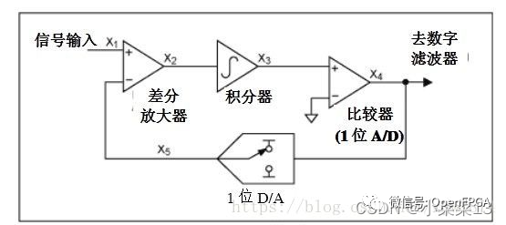
As shown in the figure above, if we add a differential at the input end of the signal, the signal is input from the positive phase of the differential, and then passes through an integrator, and then to Δ Modulator (A/D) Δ The modulated result is subject to a D/A conversion, and the delay is input to the inverse phase end of the differential as feedback, which is a complete ∑- Δ Modulator (you should know what sigma means).
The input signal is sent to the differential block, from which the feedback signal is subtracted. The generated signal is sent to the integrator, and the output of the integrator acts on the comparator. The comparator compares the reference voltage with the output of the integrator and generates "0" or "1" accordingly.
In turn, the DAC generates two available reference voltages (the highest level or the lowest level) from 0 and 1 of the ADC output. The reference voltage is fed back to the difference area. The feedback design of the differential amplifier makes the average output of DAC equal to the input signal. The output of DAC is the analog representation of the input signal, that is, the output of the modulator.
The overall quantitative approach is the same as Δ The modulation is similar, but the level of the inverted input terminal of the feedback loop differential amplifier is the maximum value (analog voltage corresponding to logic 1) or the minimum value (analog voltage corresponding to logic 0) of the entire signal, that is Δ Modulation output 1, feedback back to Vmax, output 0, feedback back to Vmin, both are fixed values.
That is to say, what the integrator integrates is the difference between the input level and the highest or lowest level, and then we will perform the integration again Δ Modulation (this process may not be so easy to figure out. Take the original signal as the derivative of a function f (x), and then we will carry out f (x) Δ Modulation and quantization, which may help us understand better).
In this way, the object of quantization becomes the difference between the current signal level and the sum of all previous differences. The quantization level will no longer be affected by the frequency, and the maximum quantization range directly depends on the level value. The delay circuit added in the feedback makes ∑- Δ The modulator has the characteristic of noise shaping, first-order sigma- Δ The noise shaping effect of the modulator is not obvious, but we can put the multiple-order Σ- Δ The modulators are superimposed to make the noise shaping effect reach a higher level.
The specific result of this noise shaping is that the total volume of quantization noise does not change, but it is not evenly distributed in all frequency bands. The quantization noise in the low frequency band will be less, and the quantization noise in the high frequency band will be more. That is to say, the quantization noise will be "pushed" to the high frequency. In the audio frequency application, most of the quantization noise will be pushed to the high frequency band that is far more than 20 kHz, which is not audible to the human ear, These noises can be easily eliminated by using a low-pass filter.
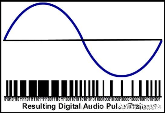
PDM is after the above Σ- Δ If the digital signal obtained by modulation is placed on the same scale and compared with the original signal, the number "0" and "1" will change with the increase or decrease of the signal frequency, so it is called Pulse Density Modulation.
From the perspective of actual engineering design, a typical PDM microphone should have power supply pin, ground pin, clock input pin, data output pin and channel selection pin * *. According to the status of the channel selection pin, the output of the microphone is active when the clock signal is at low level or high level, and at high impedance in another state. This smart design means that two microphones can be multiplexed with one microphone cable, so the stereo PDM interface only needs two cables, the real-time clock output cable and a data return cable that supports two channels at the same time.
At the application receiver using PDM as the analog-to-digital conversion method, it is necessary to use a decimation filter to convert the dense density components represented by 0 and 1 into amplitude components. The logic of PDM mode is relatively complex, but it only needs two signal lines, real-time clock and data.
PDM has a wide application prospect in places with strict space restrictions, such as mobile phones and tablets. In the field of digital microphone, the most widely used is the PDM interface, followed by the I2S interface. Audio signals in PDM format can be routed near circuits with strong noise interference, such as LCD screens (which means that digital signals have stronger anti-interference ability than analog signals, and PCM also has this advantage).
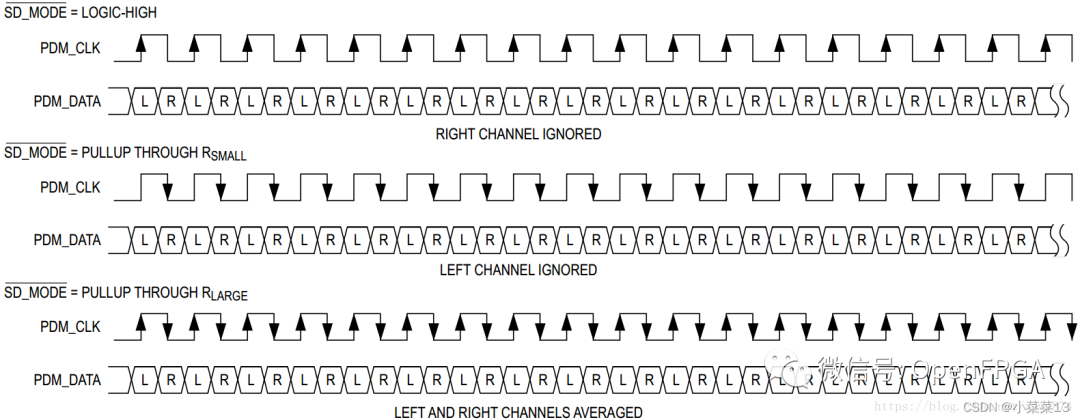
The following figure shows the requirements of Maxim‘s Class-D power amplifier MAX98358 on the timing of PDM interface. You can see it in PDM_ The rising edge of CLK samples left channel data in PDM_ The CLK falling edge samples the right channel data
MIPI SLIMbus
SLIMbus detailed introduction
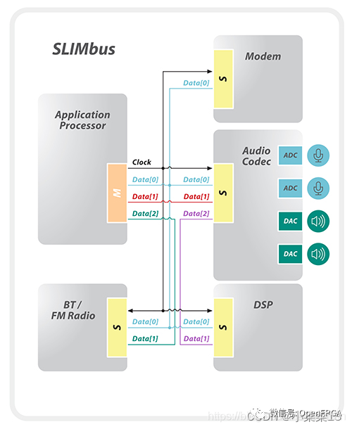
SLIMBUS, the full name of Serial Low-power Inter-chip Media Bus, is an audio interface designated by MIPI Alliance, which is used to connect baseband/application processors and audio chips. The bus protocol ensures that both control information and data information can be sent, thus replacing the traditional data and control interfaces such as I2S and I2C. SLIMbus v2.0 is a two-wire, multi-branch TDM interface that supports multiple hosts and multiple devices. It uses CMOS I/O running at a single data rate (SDR) of up to 28MHz, has a fixed frame size, and supports master control and clock switching functions to achieve low-power operation. SLIMbus v2.0 also supports multiple multi-channel, high-quality audio streams and phase coherence to achieve stereo, microphone array and other eye-catching functions. It also supports scalable bandwidth of up to eight channels per device, so that the peak aggregate bandwidth can reach 224Mbps.
MIPI SoundWire
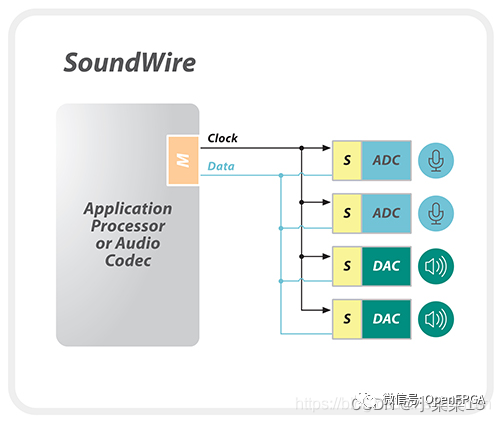
MIPI SoundWire is a supplementary specification of MIPI SLIMbus. SoundWire was launched in 2014, integrating the key attributes of audio interfaces in the mobile and PC industries, and providing a universal and scalable architecture that can be used to enable comprehensive audio functions in various types of devices in various market segments.
MIPI SoundWire is a unified interface, mainly used for small audio peripherals. It is optimized for low complexity and low gate number design to support the use of cost-sensitive audio components in mobile phones, such as digital microphones, digital speakers and advanced amplifiers. In addition, it can optimize speaker protection, microphone power and performance, noise cancellation and "always listen" audio input.
SoundWire has many SLIMbus functions. SoundWire v1.1 also uses CMOS I/O and supports up to 11 slave devices, multi-channel audio, PDM format and in-band control/interrupt/wake-up. However, it operates in dual data rate (DDR) mode up to 12.288 MHz (up to 24.576 Mbps) and supports configurable frame size and enhanced low latency protocol. Optional multi-channel expansion of up to 8 data channels can be used to support high-end audio applications. For example, eight-channel 192 KHz 24-bit audio requires 8 * 24 * 192000=36.864 Mbps, which will require two or more channels, and it may operate at a lower frequency to optimize power accordingly.
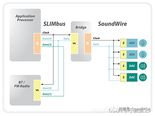
MIPI SoundWire and MIPI SLIMBus can work together in the system through bridging solutions to provide flexible and complex audio systems for mobile or mobile platforms.
SLIMbus is a mature specification with mature audio components and has been deployed in advanced smart phones and platforms affected by mobile devices. SoundWire, as the driver of digital microphone and speaker in high-end smart phone platform, is gaining rapid development momentum
other
SPDIFSony/Philips Digital Interface is the abbreviation of SONY and PHILIPS digital audio interface.
In terms of transmission mode, SPDIF is divided into output (SPDIF OUT) and input (SPDIF IN)
As far as the transmission carrier is concerned, SPDIF can be divided into coaxial and optical fiber. In fact, the signal is the same
S/PDIF is often used to transmit compressed audio signals. It is customized by IEC 61937 standard.
It is usually used in home DVD theaters that support Dolby technology or DTS surround effect, regardless of positive or negative.
A2B protocol
ADI‘s protocols for solving complex wiring settings in the vehicle include the host and slave supporting phantom power supply. Up to 32 data twisted pairs can transmit I2C control signals and data
INIC protocol
Microchip is a solution for audio and video transmission in the car, with a maximum bandwidth of 50Mbps
|
Disclaimer: This article is transferred from other platforms and does not represent the views and positions of this site. If there is any infringement or objection, please contact us to delete it. thank you! |


 Business consulting

 13823761625
 Mail me