


Application of closed-loop current sensors
Time:2023-04-08
Views:1028
Abstract: This article mainly introduces the structural principle and characteristics of closed-loop current sensors based on ASIC technology, and analyzes and explains the application advantages and examples.
1. The Best Solution for Popular Current Isolation Measurement
Due to its innovative design concept, the closed-loop current sensor based on ASIC technology has become the best solution for current isolation measurement in the industry, and is widely used in drivers, high-frequency high current measurement, UPS, and the power electronics industry, making it a product that is synchronized with the development of the power electronics industry and the needs of users. Taking LEM‘s new LTSR product series as an example, this article analyzes and introduces the characteristics and applications of its closed-loop current sensor based on ASIC technology.
The LTSR product series allows LTSR-6-NP with a rated measurement current of 6A, LTSR-15-NP with a rated current of 15A, and LTSR-25-NP with a rated current of 25A. The "R" in the LTSR represents the reference end.
The goal of the LTS25-NP series products is to find good methods for isolation measurement in the field of power electronics. Due to the widespread application of digital devices and processors in the field of power electronics, which are all powered by single ended 5V, LTSR is also powered by single ended 5V. So with the LTSR sensor, we can be closer to the field of power electronics.
LTSR can provide reference voltage for surrounding components or accept external voltage as reference voltage, such as DSP, ADC, and many very common electronic components.
Current isolation refers to the transmission of signals from the main source to the receiver without electrical coupling (i.e. no wire connection) between the main source and the receiver. In order to transmit electrical signals between current isolation circuits, magnetic field energy transformers are often used for isolation or light energy (photoconductive light-emitting element isolation).
ASIC is the English abbreviation for Application Specific Integrated Circuit, which is considered a type of integrated circuit designed for specific purposes in the field of integrated circuits. ASIC, also known as the Australian Securities and Investment Commission, is the statutory regulatory body for financial services and markets in Australia.
At present, ASIC is considered as an integrated circuit designed for specialized purposes in the field of integrated circuits. It refers to integrated circuits designed and manufactured in response to specific user requirements and the needs of specific electronic systems. The characteristic of ASIC is to meet the needs of specific users. Compared with general integrated circuits in mass production, ASIC has advantages such as smaller size, lower power consumption, improved reliability, improved performance, enhanced confidentiality, and reduced cost.
2. Basic structure
LTS-25-NP is a very small current sensor designed for PCB installation. From the perspective of new technology to new process, the R&D and production of this product is a challenge.
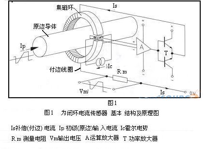
The LTSR series closed-loop current sensor is developed based on the basic structure and principle of the closed-loop principle sensor (as shown in Figure 1), so analyzing LTSR as a closed-loop principle sensor only requires an explanation of the basic structure and principle in Figure 1.
Power devices have integrated more and more new technologies. For example, switching power supply, hard switching, soft switching, parameter stabilization, linear feedback stabilization, magnetic amplifier technology, CNC voltage regulation, PWM, SPWM, electromagnetic compatibility, and so on. The actual demand directly drives the continuous development and progress of power supply technology. In order to automatically detect and display current, and to have automatic protection function and more advanced intelligent control in case of overcurrent, overvoltage, and other hazardous situations, power supply technology with sensing detection, sensing sampling, and sensing protection is gradually becoming a trend. Sensors for detecting current or voltage have emerged and are beginning to be favored by the majority of power supply designers in China.
LTSR is a closed-loop sensor based on the principle of primary and secondary magnetic field compensation. This means that the magnetic flux generated by the measured current is sensed by the Hall element in the sensor. The Hall element generates an induced current, which is supplied to the secondary coil, and then generates opposite magnetic flux in the magnetic core to compensate for the magnetic flux generated by the primary coil. The proportional reduction of the numerical value of the primary current is equal to the actual value of the current in the coil. The basic structure and principle of the closed-loop principle sensor are shown in Figure 1.
Hall elements are semiconductors that apply the Hall effect. Generally used for measuring rotor speed in electric motors, such as magnetic drums in video recorders, cooling fans in computers, etc; It is a magnetic sensor based on the Hall effect, which has developed into a diverse family of magnetic sensor products and has been widely used. Hall devices have many advantages, such as firm structure, small size, light weight, long service life, convenient installation, low power consumption, high frequency (up to 1MHz), vibration resistance, and resistance to pollution or corrosion from dust, oil, water vapor, and salt mist.
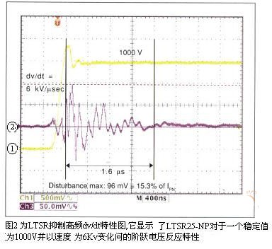
The design concept of the product is based on the following standards: small volume, 5V single ended power supply sensor. The product has a small volume and the corresponding magnetic material is also relatively small, which leads to a shorter distance between the primary and secondary edges of the sensor. This structure is beneficial for the sensor to have the ability to resist high dv/dt. This suppression of high-frequency characteristics dv/dt (curve 2-purple line shown in Figure 2) is very suitable for motor control applications. Because in motor control, the continuous conduction and shutdown of the bridge arm in the three-phase load of the motor will generate high dv/dt (as shown in Figure 2, curve 1- yellow line).
Electrical components with high insulation capacity between the primary and secondary edges can be coupled and isolated with potential. In the application environment of high-frequency switches, there will be peaks with very high frequency and large slope (such as high-speed changes in the primary voltage), which leads to unnecessary electromagnetic interference (EMI). In this case, an interference signal will be generated on the secondary output component. For example, a 10kV/ μ The parasitic current generated by the voltage change of s through a 10pF coupling capacitor is 100mA. For the LTSR series, this is 8 times the rated output current.
Note that the peak generated in the figure is IPN l5.3% interference (purple line 2), which is mainly caused by the wiring of the testing device. Note that the disturbance delay in the graph is less than 800ns, which can be filtered out (with a repeat establishment time of 1.6 μ s) This is very advantageous for PWM modulation of digital control circuits. In this case, a small filter can achieve the goal without reducing the dynamic characteristics.
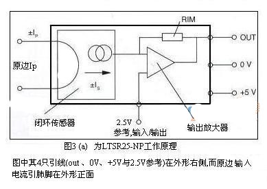
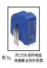
From this, it can be seen that LTS25-NP is the first current sensor to apply ASIC (Application Specific Integrated Circuit) technology. Its unique feature is the integration of magnetic field sensing elements in one layer, which can partially compensate for the changes in the HALL lattice caused by temperature drift. The working principle diagram of the LTSR series of closed-loop current sensors based on ASIC technology (now taking LTSR25-NP as an example) is shown in Figure 3 (a) and the appearance is shown in Figure 3 (b).
3.1 Has better temperature drift characteristics
The new generation ASIC technology is based on silicon crystal technology, which is different from the product LTS of the first generation ASIC technology. This technology has smaller temperature drift characteristics than the first generation. This is a very important factor for the control loop embedded in the sensor: the smaller the drift, the better the stability of the control loop.
The temperature range of LTS25-NP is -40 ℃ to+85 ℃, and within this range, the maximum bias drift we can accept is 100ppm/℃. Within the same temperature range, the structure of LTSR can reduce bias drift to 37.5 ppm/℃.
The new ASIC technology can also improve the current capacity of the driving coil and avoid output voltage dropping into the short-circuit detection area. For example, if the primary current is 10 times the rated current, and the reference voltage is 2.5V, the output voltage will not decrease by 2V and fall below 0.5V, thus not triggering short circuit detection.
3.2. Two basic operating modes of the reference voltage pin (REF) of LTSR
LTSR is a closed-loop sensor, but it has an additional reference voltage pin (REF). This pin is the reference voltage channel of the ASIC, usually set to 2.5V (as shown in Figure 3 (a)). There are two basic working modes for reference pins.
The first mode is the reference output mode (as shown in Figure 6), in which the primary current is 0A and the output voltage is consistent with the reference pin voltage (with a maximum deviation of ± 25mV between the output and reference point). A change in the primary current will not cause a change in the reference voltage.
The second mode is the reference input mode (as shown in Figure 7), in which an external voltage can be provided as a reference for this reference pin and drive the internal reference. The allowable voltage is between 1.9V and 2.7V. The source electrode can absorb or provide a minimum source current of 1mA. This is necessary to ensure that the external reference voltage drives the internal reference voltage.
When the temperature is 25 ℃ and the reference current Iref is equal to 0, the internal reference voltage is equal to 0. The reference voltage is related to the following conditions:
*The reference output mode, the reference current Iref, is determined by the connected load. To ensure that the reference point is at 2.5V ± 25mV, we apply a minimum load of 220k Ω to ensure Iref, which is the minimum. In the reference output mode, the source current should be higher than -125pA. Below this value, voltage drop will occur.
*The situation where the current is provided by an external reference (reference input mode). In the reference input mode, an external reference source can absorb or provide a current that matches the voltage, Vref=f (Iref). (When the external reference voltage is greater than the internal reference voltage Vref=2.5V ± 25mV or the external reference voltage is less than the internal reference voltage Vref).
The interconnection between sensors and other devices (such as ADC) is very simple using external reference mode (as shown in Figure 7). Based on the ASIC structure, this feature will have some impact on the measurement range. For example, if the reference point is 1.9V, the measurement range of reverse current will be 0.6V less than the provided value, and the same is true for forward current.
3.3 Wide frequency band range
The excellent coupling characteristics are also reflected in the bandwidth characteristics, as shown in the curve in Figure 4. The frequency band variation of LTSR is approximately 0.3dB. Due to the influence of devices and Hall devices, when the input current frequency is 100kHz, the response frequency band change will reach a peak. Until now, from 100kHz to 200kHz, the frequency band change of the LEM closed-loop current sensor is 3dB.
The part of the radio spectrum that lies between two specific frequency boundaries.
The unit of frequency band is Hertz (Hz).
For a channel, a frequency band is the frequency range between the highest frequency of the signal allowed to be transmitted and the lowest frequency of the signal allowed to be transmitted (of course, attenuation must be within a certain range). If there is a significant difference between the two, it can be considered that the frequency band is equal to the highest frequency of the signal allowed to be transmitted. For a signal, the frequency band is the frequency range between the highest and lowest frequencies contained in the signal (of course, the frequency component must be greater than a certain value). If there is a significant difference between the two, it can be roughly assumed that the frequency band is equal to the highest frequency of the signal.
3.4. Accurate and fast response characteristics
Fast power switching device: IGBT requires very fast overcurrent detection as protection for IGBT. For 30A/ μ The change in current at the speed of s, in fact, the secondary output will not have any delay in the change in primary current. Due to the excellent coupling characteristics between the primary circuit and the compensation coil, LTSR performs so well.
3.5. Excellent accuracy and temperature stability
The overall accuracy of the LTSR series current sensor is higher than ± 0.2% at 25 ℃. The overall accuracy value includes all tolerance indicators of the sensor.
Compared to most closed-loop current sensors that output current values, the LTSR series current sensors are built-in current sensors that measure resistance with an accuracy of ± 0.5% and a maximum temperature drift of 50ppm/K.
The internal reference point has stable temperature stability, with a maximum of 50ppm/K at (-10 ℃+85 ℃) and a maximum of 100ppm/K at (-40 ℃... -10 ℃). In most cases, the absolute accuracy of the reference point is not very important for the LTSR series due to external auxiliary circuits or digital processor control (reference output mode). (A similar situation also lies in the zero drift indicator)
Although the external reference voltage is provided by the user‘s external circuit, the voltage drift is controlled by the processor. In this case (reference input mode), you can provide the sensor with a reference voltage between 1.9 and 2.7V, but this voltage is lower than the control capability of the processor, so the voltage bias is called corrected, and the thermal offset is also called corrected.
The output voltage Vout of 3.51 LTSR25-NP has maximum temperature stability at -10 ℃...+85 ℃
*Compared to Vref, Vout has a bias of 37.5ppm/K within the operating temperature range.
*Compared to 0V, the bias of Vout in the operating temperature range is 87.5ppm/K, and it is 137.5ppm/K from -40 ℃ to -10 ℃.
87.5ppm/k is obtained by adding Vout‘s deviation from Vref (37.5ppm/k) and Vref‘s deviation from 0V of 50ppm/K.
137.5ppm/K is because the Vref bias is equal to a working temperature range of 37.5ppm/K, with a bias of 100ppm/K from -40 ℃ to -10 ℃.
As explained earlier, if the controller can compensate for the drift and bias of Vref, as well as the initial bias of Vout at Ip=0, you can improve accuracy. Within the working temperature range, increasing tolerance can achieve higher accuracy.
4. Main parameter characteristics
Table 1 presents some of the main parameter characteristics of the LTSR current sensor.
The power supply voltage is 0 to 5V, which matches the power supply voltage of many controllers. Compared with previous closed-loop current sensors, the measurement range of LTSR can be three times the rated current. This improvement is very beneficial for application. The maximum measurement range of the LTSR25-NP series is 80A at a rated current of 25A. The reference point is 2.5V (reference input mode and reference output mode), accurate to half of the power rail voltage. The range of amplifier variation is 0.625V/IPN, so the output voltage is 4.5V at+80A and 0.5V at -80A (in reference output mode).
5. Application of the LTSR series of closed-loop current sensors based on ASIC technology
5.1 Wide application range and flexible device selection
The LTSR series sensors have more additional topology functions than the previous generation products. In many application environments, the sensor output can be easily connected to ADC and input data into DSP or other microcontrollers.
Digital Signal Processing (DSP) is an emerging discipline that involves many disciplines and is widely applied in many fields. Since the 1960s, with the rapid development of computer and information technology, digital signal processing technology has emerged and developed rapidly. Digital signal processing is a method of processing real-world signals represented by digital sequences by using mathematical techniques to perform transformations or extract information. Over the past twenty years, digital signal processing has been widely applied in fields such as communication. Semiconductor manufacturers such as Texas Instruments and Freescale have strong capabilities in this field.
The LTSR is designed to directly connect to a 5V powered DSP, but currently some DSP or ADC power supplies are 3.3V. The internal reference point voltage of these 3.3V power supply chips is 1.8V. In this case, the internal reference voltage of the DSP can be used as the reference voltage of the sensor. This connection method can eliminate reference temperature drift.
In addition, the internal reference of the sensor can be used to provide a reference voltage to the ADC. It is also possible to use three sensors to connect the reference pins together. The reference point voltage will be taken as the average of the three internal reference voltages, as shown in the reference output mode of LTSR in Figure 5. This indicates that the sensor is in the reference output mode and a reference signal is provided to the ADC as a typical application diagram.
This connection method can also be applied to the reference input mode, as shown in Figure 6 for the schematic diagram of LTSR reference input mode and ADC connection. It has been demonstrated that the reference input function of applied sensors can be used to synchronize several sensors, keeping the reference voltage at the same level. Due to the 47nF capacitance at the internal end of the LTSR, it may cause a voltage increase in the external amplifier. Therefore, the output resistance of the amplifier in Figure 6 is 10 Ω to avoid an increase in the output voltage of the amplifier.
Figure 7 shows the reference output connected to a differential amplifier to eliminate output bias.
ADC, also known as Mobile ADC, is the abbreviation for Application Data Center. It is actually the evolution of the combination of ASP mode and IDC business. It is a mobile information product business launched by China Mobile, mainly targeting small and medium-sized enterprises and belonging to the mobile information industry application. The business mainly includes four industry application hosting solutions, including mobile OA, mobile email, wireless website, and mobile inventory.
5.2. Multiple Input Methods for Primary Circuit
The LTSR has three U-shaped primary connection terminals and an additional primary threading circular hole, providing designers with a flexible and diverse range of choices in current measurement. Figure 8 illustrates the internal connection method of LTSR.
The first mode: parallel connection. This can measure the maximum primary current.
The second mode: series connection. Although the measurement range is reduced, the accuracy is improved three times in low current measurements.
The third mode: micro current measurement. Measure different currents I1-I2. I2 is the current flowing through the hole, with a certain gap distance from the printed circuit board. The direction of the current varies, and the induction measurement values also vary.
5.3 Application examples
5.31. Measurement of electrical isolation current in frequency converters
The typical application of LTSR is on classic frequency converters. Due to its excellent accuracy and dv/dt suppression, LTSR is also very suitable for servo driver applications. Figure 9 is a schematic diagram of the application of electrical isolation current measurement in frequency converters. Its advantage lies in its excellent linearity, which is very suitable for motor current measurement; It also has fast responsiveness for short circuit protection, which can protect against short circuits and leakage; And good temperature stability, suitable for precise and repeatable measurements, as well as the ability to suppress strong capacitive current changes in long-distance motor wiring.
The English translation of the frequency converter is VFD (Variable frequency Drive), which may be one of the few examples of modern technology‘s reverse translation from Chinese to English. (However, VFD can also be interpreted as Vacuum fluorescent display, so this translation is not commonly used). Frequency converter is the application of frequency conversion technology and microelectronics technology to control the power transmission components of AC motors by changing the frequency and amplitude of the motor‘s working power supply. Frequency converters were once known as VVVF due to the influence of Japanese manufacturers in Asian regions such as China and South Korea. A frequency converter is an electrical energy control device that utilizes the on-off effect of power semiconductor devices to convert a power frequency power supply to another frequency. It can achieve soft starting, variable frequency speed regulation, improve operating accuracy, change power factor, overcurrent/overvoltage/overload protection, and other functions for AC asynchronous motors.
5.32 Application of current monitoring and regulation:
*The LTSR series can be applied wherever precise monitoring and adjustment of current is required. This application is suitable for AC measurement systems.
*Nonlinear loads generate non sinusoidal waves containing square waves.
The LTSR series sensors are also suitable for this application as they can measure AC or DC. LTSR can also be used in DC devices, such as power supplies, battery devices, or DC drives.
It should be noted that the LTSR series has the following advantages compared to splitters: lower energy loss in high-frequency high current measurements; Electrical isolation; Better EMI features.
6. Conclusion
6.1 Summarize the advantages of all LTSR
Single ended power supply 0/5V, capable of measuring positive and negative currents; Can output internal reference voltage Ref output mode; The external power supply provides a reference voltage to the sensor, which is the Ref input mode; High temperature stability and small temperature drift; The concept of multi range measurement can enable the same sensor equipment to cover more primary current measurement spans; Low energy loss; The closed-loop principle provides excellent linearity, wide frequency range, fast response time, wide measurement range, and the ability to measure high-frequency current pulses; Easy to install; Competitive cost control solutions.
6.2 In terms of application
LTSR can be applied to low-power electronic systems, such as frequency converters, industrial heating drive devices, ventilation devices, air conditioning devices, and many other industrial applications; For example: servo, small UPS, power and amplifier energy management system, forklift, and commonly used current monitoring.
|
Disclaimer: This article is transferred from other platforms and does not represent the views and positions of this site. If there is any infringement or objection, please contact us to delete it. thank you! |


 Business consulting

 13823761625
 Mail me