


Calculation of amplifier noise figure
Time:2023-04-30
Views:981
abstract
This article briefly introduces the noise figure calculation of two amplifier architectures, including the noise figure calculation of inverting and non inverting architectures, and provides calculation tools.
Abstract: this article introduce the noise figure calculation of several architecture, such as inverting, non-inverting, And also provide the calculation tool.
Key words: Noise figure, Inverting, non-inverting.
introduction
In various situations where amplifiers are used, we often need to calculate the amplifier, but there is no intuitive way to see the impact of the amplifier stage on link noise. This article discusses the calculation methods of the noise figure of amplifiers under various amplifier architectures.
Amplifier noise index
In the application of electronic components, there are five common sources of noise:
1. Shot noise (white noise, flat in the spectrum)
2. Thermal noise (white noise, flat in the spectrum)
3. flicker noise (1/f noise)
4. Burst noise
5. Avalanche noise (noise that only appears during reverse breakdown)
Basically, each amplifier has two indicators: input voltage noise and input current noise. In the frequency domain, its units are usually represented by nV/rtHz and pA/rtHz. As shown in the following figure:

Figure 1 Legend of Input Voltage Noise and Current Noise Curve
According to the type of noise, its approximate contribution in different frequency bands is as follows:


Figure 2: Distribution of Noise Types
If all capacitors and inductors are considered as noise free devices, the output noise of an ordinary amplifier can be mainly contributed as shown in the following figure:
Figure 3 Amplifier noise component decomposition
The noise representation form of resistance is 4kTR, K is Boltzmann constant, K=1.3806505 × 10⁻²³J/K, T is the ambient temperature, expressed in Kelvin (K), K=273.15+degrees Celsius. Based on these parameters, the voltage noise contribution formula for estimating resistance noise can be simplified as follows, with the unit being nV/rtHz
Based on this estimation, the voltage noise of the following resistance values can be obtained:
In the output noise, the contributions of each component in the figure above are as follows:
The output noise is the sum of the mean squares of these components:
If you carefully observe this formula, you will find that the calculation has been simplified. 1) 2) 3) The component comes from the voltage noise of the positive input, and its equivalent gain to the output is equal to the noise gain, which is 1+RFRG. 4) and 6) are the current noise from the negative input, where 4) are the negative current noise of the operational amplifier itself, and 6) are the current noise converted from the voltage noise of RG, and their output gain is RF, 5) The term is the voltage noise caused by RF, which is reduced to an output gain of 1.
Regarding the noise introduced by resistors (RF and RG, items 5 and 6 in the above equation), if converted into voltage noise, it can also be calculated according to the following assumptions, and the results obtained are the same:

Figure 4 Amplifier Voltage Noise Equivalent Output Model
Similarly, for the fourth item in the above equation, the current noise at the negative end can also be modeled as follows:

Figure 5 Amplifier Current Noise Equivalent Output Model
Gains here are all noise gains: 1+Rf/Rg
The final result obtained is also the same as the fourth item above.
Signal to noise ratio calculation
The above calculation is only limited to the calculation of noise spectral density. In practical applications, the main concern is the signal-to-noise ratio, which requires the introduction of a very important point in noise calculation: bandwidth. So it is also necessary to consider the total noise after bandwidth integration.
After obtaining the voltage noise density within a certain bandwidth, it is necessary to convert the voltage noise to the success rate in order to perform integration calculations. Instead of directly integrating the voltage noise, we assume that we know the voltage noise density of an amplifier to be 5nV/rtHz. If we want to calculate the integration noise within 10Hz, we will proceed as follows:

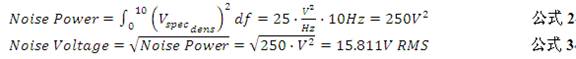


Figure 6 Calculation of comprehensive noise through noise spectral density
As we mentioned above, the noise distribution of the amplifier is divided into regions. If the filtering effect of the channel is also taken into account, the steps to calculate the integral noise are as follows:
Figure 7 Frequency distribution diagram of spectral density of input voltage noise and current noise
1. 1/f noise area (en1/f)
Figure 8 1/f noise
Assuming the highest level noise is e1/ f@1Hz , then
2. Flat band region+filter effect (enBB)
Figure 9 Flat band noise
|
Disclaimer: This article is transferred from other platforms and does not represent the views and positions of this site. If there is any infringement or objection, please contact us to delete it. thank you! |


 Business consulting

 13823761625
 Mail me