


Appliance motor drive applications - SiC power devices bring higher energy efficiency and power density
Time:2023-07-09
Views:775
Over the past few decades, various energy regulations have emphasized the importance of manufacturing energy-saving products. This greatly promotes energy conservation and consumption reduction [1]. In addition, these regulations and standards pave the way for designing more innovative household appliances by utilizing the excellent characteristics of new technologies such as SiC MOSFET. The adoption of these technologies helps manufacturers obtain certification for the highest energy efficiency level.
Text: Infineon Technologies Konstantinos Patmanidis, Stefano Ruzza, Claudio Villani
introduction
Not long ago, Infineon launched a newly developed Advanced Integrated Success Device (IPD) IM105-M6Q1B. The IM105-M6Q1B adopts a 7mm x 7mm quad leadless flat package (QFN), integrating the many advantages of Infineon CoolSiCTM technology and the highly reliable high-voltage drive integrated circuit (IC) that can be regarded as an industry benchmark. By using this set of success rate devices (IPD), low-power motor drivers with higher power density can be designed, while breaking through limitations and expanding the output power range under operating conditions without heat sinks.
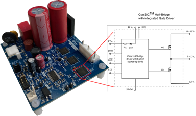
As shown in Figure 1, a test driver board was designed to test the performance of IM105-M6Q1B under typical refrigerator compressor load conditions. The diagram also provides a block diagram of IM105-M6Q1B. The components of IPD include a SiC MOSFET half bridge (with a typical on state resistance of 257 m Ω at Vgs=18 V and Tj=25 ° C) and a gate driver based on silicon on insulator (SOI) technology. Compared to the 600 V blocking voltage of standard devices, its maximum blocking voltage has increased to 650 V, providing greater withstand voltage margin when the grid voltage fluctuates. The advantages of Infineon SOI technology for gate drivers lie in high switching frequency [3], low ohmic (30 Ω) monolithic integrated bootstrap diodes [3, 4], and strong anti-interference ability against negative transients caused by inductive load switching process [5]. In addition, the grid driver provides a fixed internal Dead time, which is usually 540 ns. As long as the external Dead time is smaller than this value, it will be automatically inserted to achieve the through protection of the upper and lower bridges. All of these gate driver functions, as well as the advantages of Infineon CoolSiCTM technology, are integrated into a small surface mount device (SMD) package.
Figure 1: Block Diagram of Drive Board Test Vehicle and IM105-M6Q1B
On state output characteristics
This section explores the typical output characteristics of IM105-M6Q1B under two gate bias voltages (15 V and 18 V). In the small power home appliance motor driver market, two commonly used products are IKD04N60RC2 and IPD60R280PFD7S. This section also compares their output characteristics with IM105-M6Q1B.
The first output characteristic diagram is shown in Figure 2. It can be seen that in the first quadrant operation, the pressure drop of IM105-M6Q1B is significantly lower than (about 4A) the pressure drop of IKD04N60RC2. In addition, in general, the RDS (on) temperature dependence of IM105-M6Q1B is only 0.11 m Ω/° C at Vgs=15 V, and slightly higher at 0.2 m Ω/° C at Vgs=18 V. This highlights the extremely temperature dependent feature of CoolSiCTM technology. On the other hand, during the third quadrant operation during diode conduction, the voltage drop of IM105-M6Q1B is higher than that of IKD04N60RC2. However, please note that the diode is only turned on within the Dead time. Under application conditions, the Dead time is about 0.5 to 1 µ s, so the loss caused by it is insignificant. When the SiC MOSFET channel conducts in the third quadrant operation, the voltage drop is slightly lower than that in the first quadrant operation.
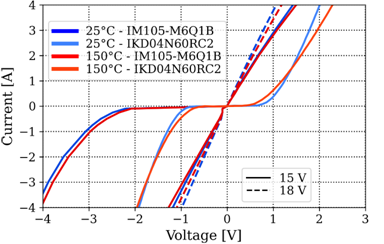
Figure 2: Comparison of on state output characteristics of IM105-M6Q1B with IKD04N60RC2
Figure 3 shows the second comparison graph. Obviously, under the condition of Tj=25 ° C, the pressure drop of IPD60R280PFD7S in the first quadrant operation is lower than IM105-M6Q1B. When Vgs=10 V and Tj=25 ° C, the typical RDS (on) of IPD60R280PFD7S is 233 m Ω. As listed in the data table, increasing gate bias does not further reduce the voltage drop for this device type. In addition, it can also be seen that the pressure drop temperature dependence of IPD60R280PFD7S is significantly higher than that of IM105-M6Q1B. The typical RDS (on) temperature dependence of IPD60R280PFD7S is about 2.53 m Ω/° C, so when the junction temperature increases, its conduction loss will be higher than IM105-M6Q1B. Similarly, when the diode is subjected to forward bias, the voltage drop of IPD60R280PFD7S is lower than that of IM105-M6Q1B.
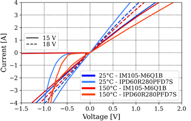
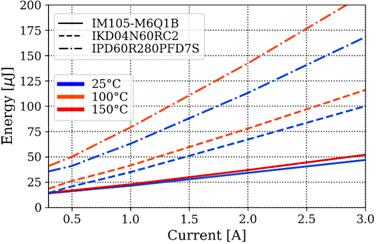
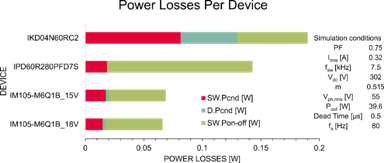
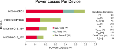
Figure 3: Comparison of on state output characteristics of IM105-M6Q1B with IPD60R280PFD7S
Finally, Figure 4 shows the typical total dynamic loss values of the aforementioned devices, which were measured using a typical dual pulse testing device. Please note that this analysis does not include reverse recovery losses as their impact on total losses is relatively small. The voltage change rate dv/dt of both devices is adjusted to around 6.5-7 V/ns to ensure fair comparison. The switching speed of IM105-M6Q1B is internally adjusted to 6 to 7 V/ns (20-80%) by its integrated gate driver.
Tests have shown that compared to IKD04N60RC2, especially IPD60R280PFD7S, the power loss of IM105-M6Q1B is much lower, and its power loss mainly depends on conduction loss. Finally, the temperature dependence of the dynamic loss of IM105-M6Q1B can be ignored, while for other devices, even when Tj=100 ° C, the loss begins to significantly increase.
Figure 4: Sum of dynamic losses on and off under different switching current and temperature conditions
Simulation analysis of typical refrigerator compressors
The complete working cycle of a typical refrigerator compressor includes multiple working points. The two most unique operating points are the rated operating point (with an output power of approximately 40 W) and the high load operating point (with an output power of approximately 160 W). This analysis used PLECS ® Software tools to simulate and calculate the power loss of three devices. Figures 5 and 6 show the simulation results and typical application conditions. In these simulations, the shell temperature is set to Tc=110 ° C. Due to material characteristics, this is usually the highest working shell temperature for printed circuit boards (PCBs). Under light or rated load conditions, the loss of IM105-M6Q1B is nearly 43% lower than that of IPD60R280PFD7S and 60% lower than that of IKD04N60RC2. Under these conditions, increasing the gate voltage to Vgs=18V does not bring significant benefits.
Under high load conditions, the loss of IM105-M6Q1B is nearly 37% lower than that of IPD60R280PFD7S and 64% lower than that of IKD04N60RC2. In this test, increasing the gate voltage of IM105-M6Q1B to Vgs=18V reduced the loss by 14% compared to the gate voltage Vgs=15V, which is the lowest loss that IM105-M6Q1B can achieve.
Figure 5: Power loss segmentation diagram of a typical refrigerator compressor under specific rated load conditions
Figure 6: Power loss segmentation diagram of a typical refrigerator compressor under specific high load conditions
The efficiency calculation of the inverter level is shown in Table 1. This analysis considers a two-level three-phase inverter, which consists of a total of 6 devices. Under nominal load, the total efficiency increase of IM105-M6Q1B is 2.7% more than IKD04N60RC2 and nearly 1% more than IPD60R280PFD7S. Under high load conditions, compared to IKD04N60RC2 and IPD60R280PFD7S, the efficiency increased by approximately 1.5% and 0.5%, respectively.
|
device |
Efficiency [%] |
|
|
Nominal load |
high-load |
|
|
IM105-M6Q1B_18 V |
98.77 |
99.29 |
|
IM105-M6Q1B_15 V |
98.74 |
99.17 |
|
IPD60R280PFD7S |
97.82 |
98.69 |
|
IKD04N60RC2 |
96.95 |
97.75 |
Table 1: Efficiency calculation of 6-bridge two-level three-phase inverter
Hardware Experiment Results
This section discusses the additional benefits of IM105-M6Q1B in terms of appearance (i.e. power density). In addition, a comparative analysis was conducted on the output power capability of low-power drive boards with similar designs without heat sinks using IKD04N60RC2 and IM105-M6Q1B. Figure 7 shows the images of these two driver boards side by side to clearly highlight their differences. Both driver boards are equipped with similar electromagnetic interference (EMI) filters, diode rectifiers, DC link capacitors, and microcontroller IMC101T-038 (iMOTION ™ IMC100 series motor controller).
Both designs use double-layer boards and 35 µ m copper foil thickness for layout. The main difference lies in the inverter level. The driver board using IKD04N60RC2 requires 6 IGBT transistors packaged in TO-252 and a full bridge three-phase gate driver IC to form a two-level three-phase inverter. On the other hand, thanks to its integration of half bridge and gate drivers into the QFN package, the space required for using the IM105-M6Q1B driver board is much smaller. Therefore, the size of this driver board can be reduced by 15%, thereby increasing power density.
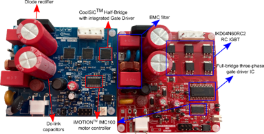
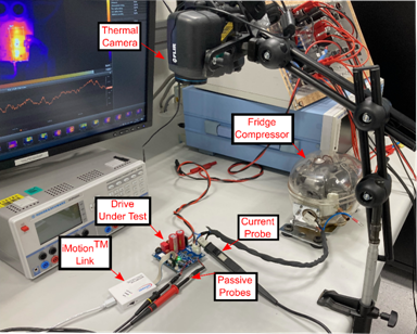
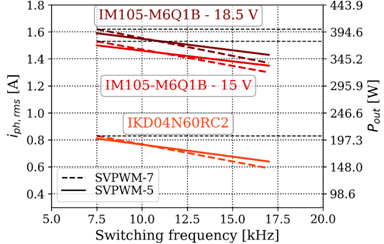
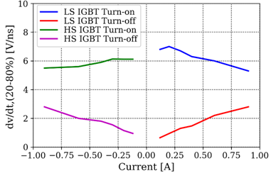
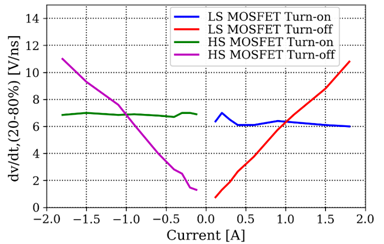
Figure 7: Low power consumer driver application: Blue PCB (left) using IM105-M6Q1B, size: 66.4 mm x 78 mm; Red PCB (right side) using IKD04N60RC2, size: 78 mm x 78 mm
The switching frequency (fsw) of low-power home appliance motor drive applications such as refrigerator compressors, circulation pumps, etc. is usually between 7.5 and 17 kHz. Most of these applications are not equipped with heat sinks because their low output power ensures that the power switch operates within the specified thermal limit range. As mentioned earlier, their maximum allowable shell temperature (Tc, max) is limited to around 110 ° C.
In order to study and analyze the performance of the driver under test conditions, a typical refrigerator compressor was selected. Figure 8 shows a laboratory test bench using a refrigerator compressor as a load. Use a thermal imager to monitor the top shell temperature of the inverter. The control scheme is implemented using Infineon‘s iMOTIONTM IMC101T-T038 microcontroller and isolated debugging probe iMOTIONTM Link. The tested driver directly supplies power to the DC link to avoid any grid voltage fluctuations or load effects on the voltage, and supports the use of standard passive probes without the need for floating measurement equipment. Connect the passive detector to a low side power device to measure the typical dv/dt behavior of the device. Finally, connect a current probe in the output phase to monitor the motor current.
Figure 8: Laboratory test bench
Two modulation techniques were used, one is 7-segment space vector pulse width modulation (SVPWM), and the other is 5-segment space vector pulse width modulation (SVPWM) (which can reduce switching losses), as described in [6]. Table 2 lists the experimental testing conditions. For all experimental conditions, the DC link voltage is preset to 310 V, powered by a high-voltage DC power supply unit. The output fundamental frequency (fs) of the refrigerator compressor is configured as 20 Hz. The ambient temperature (Ta) is approximately 25 ° C at room temperature. The power factor (PF) was not measured to avoid any additional parasitic effects. The only independent experimental variable is the modulation coefficient. Adjust the modulation coefficient until the inverter reaches the highest shell temperature, thereby obtaining different allowable phase currents. Using an open-loop control scheme for regulation, in this experiment it is referred to as V/f control, as it only focuses on the inverter level. These experiments can demonstrate the maximum output power capability of the drive board.
|
Vdc [V] |
310 |
|
fs [Hz] |
20 |
|
Ta [℃] |
25 |
|
fsw [kHz] |
7.5–17 |
|
Vgs–Vge [V] |
0–15, 18.5 |
|
Tc,max [℃] |
110 |
|
Dead Time [µs] |
1 |
Table 2: Experimental Test Conditions
Figure 9 shows the output power capability. The output power calculation in the figure takes into account a PF of 0.75 and an amplitude modulation index of 1. Obviously, the output power of IM105-M6Q1B is almost twice that of the IKD04N60RC2 driver board, which also proves its higher power density. Compared to the test under the condition of Vgs=15V, in this test, the gate voltage increased to approximately Vgs=18.5V, which resulted in a 6% increase in output power.
Figure 9: Maximum allowable phase current under different switching frequencies and modulation schemes
Finally, Figures 10 and 11 show the typical dv/dt behavior of the two devices used in this test. The high side switch is represented by HS, and the low side switch is represented by LS. Please note that the conduction dv/dt of IKD04N60RC2 is set to approximately 6 to 7 V/ns.
Figure 10: Voltage change rate (dv/dt, 20-80%) of IKD04N60RC2 driver board set to 6.5 V/ns at Tc, max under different switching currents
Figure 11: Voltage change rate (dv/dt, 20-80%) of IM105-M6Q1B driver board under different switching currents at Tc and max
epilogue
The newly issued energy efficiency labeling directive for low-power motor drive applications (i.e. household appliances) emphasizes the importance of developing innovative solutions and adopting new semiconductor technologies to achieve the highest energy efficiency level. This article introduces the multiple advantages of Infineon CoolSiCTM MOSFET implemented in the integrated product IM105-M6Q1B. A small QFN package with a size of only 7 mm x 7 mm can help design system level solutions with higher power density. In order to highlight its advantages, a driver board based on IM105-M6Q1B was designed, which has a size reduction of 15% compared to the IKD04N60RC2 based split solution. The output power processing capability of IM105-M6Q1B is also significantly better than that of IKD04N60RC2. Moreover, using IM105-M6Q1B can improve the efficiency of the inverter by 1-2.7%.
|
Disclaimer: This article is transferred from other platforms and does not represent the views and positions of this site. If there is any infringement or objection, please contact us to delete it. thank you! |


 Business consulting

 13823761625
 Mail me