


Common Problems in the Application of Chip Resistors
Time:2023-08-01
Views:698
Abstract: In the modern electronic industry, chip resistors are often the most common internal devices in electronic products, but they are often overlooked by us, leading to various unpredictable product failures.
The rated working voltage is linked to power, and the maximum working voltage is the maximum voltage that the resistor can withstand at rated power. But be careful! Look at the picture below. It can be seen that the rated power is marked under the highest ambient temperature of 70 degrees Celsius (there may be slight differences between different manufacturers and series, and it should be verified clearly at the beginning of design and during problem finding.)


Perhaps you have tried the product before, but after a period of customer use, the circuit failed for no reason. The circuit may appear intact, or it may have burned a large area. When you can‘t find a problem after racking your brains, it‘s best to focus on those small chip resistors first.
1.1 Two Key Parameters and Derating Curve
Let‘s take a look at the parameter table of four commonly used packaging resistors from a certain manufacturer. There are two values in the table: rated working voltage and maximum working voltage.
| package | Rated power (W) | Maximum rated voltage (V) | Maximum working voltage (V) |
| 0402 | 1/16 | 50 | 100 |
| 0603 | 1/10 | 75 | 150 |
| 0805 | 1/8 | 150 | 300 |
| 1206 | 1/4 | 200 | 400 |
Figure 1 Resistance Temperature Derating Curve
Under the condition of overpower, there are generally two situations for resistors: 1. Instantaneous overpower. The appearance of the resistor remains basically unchanged, but the resistor is already open. 2. Long term overpower: The resistance temperature is extremely high, and its resistance value changes. If under harsh conditions, it will burn out the open circuit.
Figure 2: Instantaneous power damage, with almost no change in appearance, but actually an open circuit
Figure 3: Long term overpower, high temperature direct carbonization and burning of resistance
1.2 PCB board also pays attention to detail
Another common damage to SMD resistors is that they become open circuit after mechanical damage, which subsequently leads to circuit abnormalities (the appearance of the device may be normal). Here are a few small suggestions: 1. If it is a hand folded board (rarely used, unable to machine divide the board, with high burrs), the length direction of the chip resistor is parallel to the edge of the PCB board, and the stress on the parts is small; If it is V-CUT, the length direction of the SMD device is perpendicular to the PCB edge, and the possibility of part breakage is relatively low. 2. If the component is perpendicular to the connection, the recommended distance to the connection should be ≥ 4mm, and if it is parallel, the recommended distance should be ≥ 1.5mm. 3. If cost allows, appropriately thicken the PCB board thickness, especially for larger boards. (Below are two simple schematic diagrams, please analyze the actual situation.)
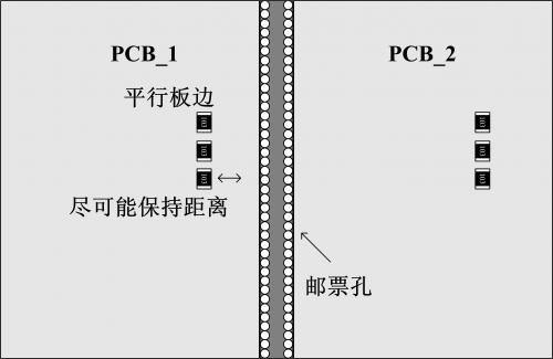


Figure 4 Simple schematic diagram of hand folding board
Figure 5 Simple schematic diagram of V-CUT board
1.3 Reasonable reduction of types
The following figure shows the oxidized patch resistors of two electrodes (with a slightly black surface). Despite their current condition, once the circuit enters a harsh working state (high temperature and humidity), the resistors will work in an unpredictable state due to faulty soldering, leading to damage.
Figure 6 Resistance of oxidation
In addition to ensuring that the purchased resistors are within their shelf life and that the warehouse provides a suitable storage environment (refer to the actual product manual for details), our engineers, as users, also try to minimize the use of resistors with special resistance values to reduce this risk.
Although SMD resistors are known for their stable performance, if we can tirelessly recall some details at the beginning of each use, we can minimize the occurrence of small accidents and greatly improve product stability.
|
Disclaimer: This article is transferred from other platforms and does not represent the views and positions of this site. If there is any infringement or objection, please contact us to delete it. thank you! |


 Business consulting

 13823761625
 Mail me