


How to efficiently generate high-voltage power rails in automotive applications
Time:2023-08-10
Views:673
Although 12V lead-acid batteries are still the mainstream of automotive power supply, there are also some new applications that require higher voltages, such as mainline audio power amplifiers and window defrosting devices. To meet the requirements of these high-voltage applications, a new generation of AEC-Q100 certified synchronous boost controllers has emerged in the market. This controller is designed to increase the battery voltage by 12V, withstand spikes of up to 60V, and have the high reliability required by new vehicle models.

This article introduces a pair of easy-to-use 2-phase 55V synchronous boost controllers that can generate 24V, 36V, or 48V power rails in automotive environments with only 12V power supply. We will study some of the main functional features integrated with them, including comprehensive protection functions that help achieve optimal solutions, thereby reducing costs and improving efficiency, safety, and reliability. We will also discuss an integrated PMBus interface that provides advanced control, telemetry, and diagnostic functions, and simplifies the task of achieving ISO 26262 compliance.
Increase the 12V battery voltage
A challenge that system design engineers always face is how to achieve higher power efficiency while minimizing circuit board space. The method to solve this problem with the ISL78227 and ISL78229 55V synchronous boost controllers is to integrate advanced FET drivers, which can adaptively adjust the number of switches to prevent cross conduction phenomenon when simplifying power stage design. The 2-phase configuration adopted by these two controllers can reduce ripple current, allowing for the use of smaller input and output capacitors, which helps to reduce the circuit board footprint. Two controllers can be used in parallel to increase the number of phases to four, thereby supporting higher power output levels.
ISL78227 and ISL78229 come with a PMBus interface, supporting a wide operating frequency range of 50kHz -1.1MHz, and can be configured by using smaller external components to optimize the operating frequency, thereby helping to improve efficiency or minimize circuit board space. They include many functional features aimed at maximizing efficiency, which is important because the peak output current of a 12V battery under 400W load conditions will exceed 30A.
Synchronous FET for output rectification
Due to the low output voltage of most buck converters, FETs are often used instead of diodes in buck converters to achieve output rectification function. In this configuration, a large proportion of the power loss when generating output voltage comes from the voltage drop on the rectifier components. Replacing the output rectifier diode with a synchronous FET that can be turned on and off at the appropriate time can significantly improve efficiency. This is because FET losses typically account for only a small portion of the rectifier diode losses. In the buck converter, the reference voltage of the synchronous FET is the ground voltage, so the driving circuit is relatively simple.
Synchronous FETs bring many benefits to boost configurations. In the application of boost converters, the output voltage is usually several times the input voltage, so the power loss generated by the output rectifier components accounts for a small proportion of the total output power. The boost converter benefits from the efficiency improvement of synchronous FETs, which provide bidirectional current, which can support continuous mode operation (even under light load conditions) - an important advantage for applications that require low electromagnetic interference (EMI). Bidirectional current flow is also an important capability for achieving effective envelope tracking, which we will discuss in the following text. Furthermore, using synchronous FETs does not exclude operation in intermittent mode. The boost controller can detect negative current flow and can choose to disable synchronous FETs to simulate the function of synchronous rectifier diodes.
Improving Light Load Efficiency through Diode Simulation
Audio signals often undergo drastic changes in a very short period of time. At this moment, the amplifier may require a high-power burst pulse, and at the next moment, it may require a very low-power burst pulse. Intermittent audio sessions may even mute. When this situation occurs, the power consumption of the amplifier will significantly decrease, as the power demand of the boost regulator will also decrease to a lower value. In fact, under light load conditions, the boost inductor current can be reduced to zero. When this situation occurs, the output voltage (boost voltage) of the inductor is higher than the input voltage (battery voltage). If the synchronous FET remains on under this condition, the current will begin to flow in the opposite direction through the inductor and obtain charge from the output capacitor.
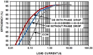
Figure 1. Efficiency vs. Load Comparison, 2-phase boost configuration, three operating modes, fSW=200kHz, VIN=12V, VOUT=36V, TA=+25 ° C
These 55V boost controllers include optional circuits to avoid this reverse conductivity loss by simulating the current blocking behavior of real diodes with synchronous FETs. This intelligent diode operation is called diode simulation mode (DEM), and its function is to turn off the synchronous FET when the circuit senses the inductance current starting to flow in the wrong direction. If the controller enters diode simulation mode and the load is still decreasing, the controller will enter pulse omission mode to reduce the number of switching cycles and improve its efficiency when very light loads occur on the output.
Although DEM can improve efficiency under light load conditions, it also poses some electromagnetic interference challenges due to the constantly changing switching characteristics. To avoid electromagnetic interference issues, the usual ideal practice is to maintain continuous conduction mode (CCM) operation. Of course, this will sacrifice the efficiency improvement brought about by diode simulation, as shown in Figure 1. However, in applications such as audio amplifiers, an alternative method to achieve light load efficiency improvement is to use the envelope tracking function of the amplifier power supply to track input requirements.
Forced PWM working mode
Many power system applications require the switching frequency of the converter to be kept constant to minimize the possibility of interference. Due to this requirement, ISL78227 and ISL78229 can also operate in PWM mode (without pulse omission). However, in forced PWM mode, it may cause reverse current flow, such as entering a pre biased output state during startup or when the output voltage rises above the expected voltage. In a typical system, there is no way to limit the reverse current, which can damage the synchronous FET. ISL78227 and ISL78229 address this issue by providing reverse current limiting functionality. Limiting negative current can reduce output voltage transients and improve system reliability. Therefore, design engineers can configure the boost controller to be in forced PWM mode without worrying about losing control of the reverse current.
Improve light load efficiency through Phase Shedding function
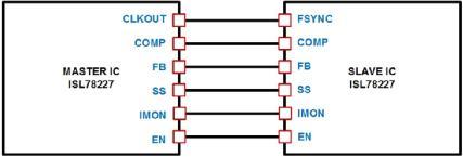
The ISL78227/29 synchronous boost controller supports 2-phase boost operation, and we can connect two devices to achieve four-phase operation (see Figure 2). Under heavy load conditions, the main system losses are due to conductive losses and switching losses, but under light load conditions, switching losses begin to become the main loss factor. To improve efficiency, both controllers can be configured simultaneously to monitor the system current level. If the load drops below a certain threshold, the controller will lose one phase, which can reduce the switching loss under light load conditions. The phase shielding process is completed within 15 switching cycles to prevent load transients. If the load subsequently increases above the threshold, immediately add a phase to manage the increased load.
Figure 2. Supporting 4-phase operation by connecting two devices to meet the requirements of higher power applications
Reference voltage control and audio envelope tracking
The output voltage of the boost controller can be adjusted using a 1.6V on-chip reference voltage, or it can be adjusted to an external tracking voltage used to drive the control circuit. The uniqueness of the ISL78227 and ISL78229 controllers is that the external signals used to drive the tracking function can be configured as analog voltage or PWM signals. These TRACK functions dynamically support changes in output boost voltage. These controllers include negative current limiting and protection functions, which are very useful in envelope tracking when flowing from higher voltage to lower voltage.
The task of outputting boost voltage was originally to track the control signal, but when the voltage changes from higher to lower, the output capacitor must be discharged to reduce the voltage. If the load itself does not consume enough current, synchronous FETs can help discharge the output capacitor without worrying about FET damage due to excessive current. This is because both controllers include negative current limiting and protection circuits for these conditions.
For audio applications where the power supply voltage changes rapidly over a wide range, it is very useful to support envelope tracking without worrying about excessive reverse current. In audio applications, the TRACK signal can be used to control the increased output voltage, allowing it to track the amplitude changes of the audio amplifier signal. This can keep the power supply voltage stable, prevent short-term pulse wave interference during load changes, and thus prevent burst sound from the audio power amplifier.
Remember, as shown in the following equation, the power delivered to the speaker is a function of the amplifier‘s peak output voltage:
Pavg=Vrms · Irms=V2rms/R=V2peak/2R
It is common to increase the 12V battery voltage in automotive audio power amplifier applications. These boost controllers can increase the battery voltage to 48V or any desired voltage to support the power level of the audio power amplifier. The power range of audio amplifiers between 100-800W is very common. Some high-quality audio systems with multi-channel systems may include amplifiers of 30-40W and a higher power amplifier for driving subwoofers.
In analog audio amplifiers, if the power supply voltage is only large enough to support audio signals, efficiency can be improved. The efficiency improvement of digital audio amplifiers depends on the digital amplifier architecture.
PMBus control
The ISL78229 boost controller shown in Figure 3 includes a PMBus interface that can help design engineers‘ systems achieve ISO 26262 compliance and meet Automotive Safety Integrity Level (ASIL) requirements. The PMBus interface is useful in systems that require real-time telemetry, error reporting to microcontrollers, and system control functions. It provides a way to remotely enable or disable boost controllers and monitor and report variables such as input voltage, input current, and output voltage. In addition, the boost controller also includes a pin to support the measurement of external negative temperature coefficient (NTC) resistance for temperature monitoring. Then, it digitizes the signal and can also report readings through PMBus. Additionally, an over temperature fault limit can be set for external temperature monitoring.
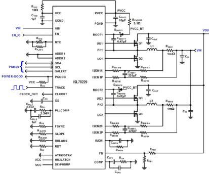
Figure 3. Typical application of ISL78229 with PMBus control
The boost controller also has fault reporting functions, such as input overvoltage, output overvoltage or output undervoltage, overcurrent, and over temperature faults. Each function can be monitored through PMBus. Adding a PMBus interface helps avoid the need for specialized telemetry circuits.
conclusion
The ISL78227/29 multiphase 55V synchronous boost controller provides many functional features that can meet many different power system requirements. These functional features may not be significant individually, but when combined, their overall effect far exceeds the sum of their respective effects. The voltage quality module used for start stop systems, trunk audio amplifiers, and window defrosting devices is only one of the few high voltage applications that require stable boost controller solutions.
|
Disclaimer: This article is transferred from other platforms and does not represent the views and positions of this site. If there is any infringement or objection, please contact us to delete it. thank you! |


 Business consulting

 13823761625
 Mail me