


Detailed explanation of the working principle of the full bridge motor drive circuit
Time:2023-08-20
Views:659
Introduction: This article will mainly introduce the working principle of H-bridge motor drive, and conduct a comprehensive analysis from two aspects: counterclockwise and clockwise.
In circuit design, the role of a full bridge is very important. When the four diodes in a bridge rectifier circuit are packaged together, they form a full bridge circuit, which is actually what we often refer to as an H-bridge circuit. This article will mainly introduce the working principle of H-bridge motor drive, and conduct a comprehensive analysis from two aspects: counterclockwise and clockwise.
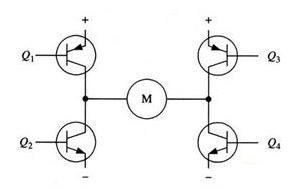
Figure 1 H-Bridge Motor Drive Circuit
Figure 1 shows a typical DC motor control circuit. The circuit is named after the "H bridge driver circuit" because its shape resembles the letter H. The four transistors form the four vertical legs of H, and the motor is the horizontal bar in H. Note: Figure 1 and the following two figures are only schematic diagrams, not a complete circuit diagram, where the driving circuit of the transistor is not shown.
As shown in the above figure, the H-bridge motor drive circuit includes four transistors and one motor. To make the motor run, a pair of transistors on the diagonal must be connected. According to the conduction of different transistor pairs, current may flow through the motor from left to right or from right to left, thereby controlling the direction of the motor.
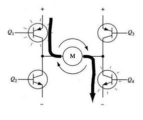
To make the motor run, it is necessary to conduct a pair of transistors on the diagonal. For example, as shown in Figure 2, when Q1 and Q4 tubes are connected, the current flows from the positive pole of the power supply through Q1 from left to right through the motor, and then back to the negative pole of the power supply through Q4. As shown by the current arrow in the figure, the current in this direction will drive the motor to rotate clockwise.
Figure 2 H-bridge circuit driving motor clockwise rotation
When the transistors Q1 and Q4 are connected, current will flow through the motor from left to right, driving the motor to rotate in a specific direction (the arrows around the motor indicate a clockwise direction).
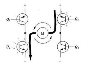
Figure 3 H-bridge circuit driving motor counterclockwise rotation
Figure 3 shows the conduction of another pair of transistors Q2 and Q3, with current flowing through the motor from right to left.
When the transistors Q2 and Q3 are connected, current will flow through the motor from right to left, driving the motor to rotate in another direction (the arrows around the motor indicate a counterclockwise direction).
Enable control and directional logic
It is important to ensure that the two transistors on the same side of the H-bridge do not conduct simultaneously when driving the motor. If the transistors Q1 and Q2 are conducting simultaneously, the current will pass from the positive electrode through both transistors and directly return to the negative electrode. At this point, there is no other load in the circuit except for the transistor, so the current on the circuit may reach its maximum value (which is only limited by the power supply performance), or even burn out the transistor.
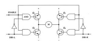
Figure 4 H-bridge circuit with enabling control and directional logic
Based on the above reasons, in actual driving circuits, it is usually necessary to use hardware circuits to easily control the switch of the transistor. Figure 4 shows an improved circuit based on this consideration, which adds 4 AND gates and 2 NOT gates to the basic H-bridge circuit. Four "enable" conduction signals are connected to the same gate, so that the entire circuit can be controlled to switch with this signal. By providing a directional input, the two non gates can ensure that only one transistor can conduct on the same leg of the H-bridge at any time. (Like the previous schematic, Figure 4 is not a complete circuit diagram, especially when directly connected to the gate and transistor in the diagram, it cannot function properly.)
By using the above method, the operation of the motor only needs to be controlled by three signals: two directional signals and one enable signal. If the DIR-L signal is 0, the DIR-R signal is 1, and the enable signal is 1, then the transistors Q1 and Q4 are connected, and the current flows through the motor from left to right (as shown in Figure 5); If the DIR-L signal becomes 1 and the DIR-R signal becomes 0, then Q2 and Q3 will conduct, and current will flow in the opposite direction through the motor.
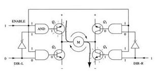
Figure 5 Use of Enable Signal and Direction Signal
When in practical use, it is very troublesome to make H-bridge using discrete components. Fortunately, there are many packaged H-bridge integrated circuits on the market now, which can be used when connected to a power supply, motor, and control signal. It is very convenient and reliable to use within the rated voltage and current.
The H-bridge circuit is often used in inverter circuits and DC motor circuits. Here, we only explain the application principle of the H-bridge circuit in DC motors. I hope everyone can fully grasp various basic knowledge of full bridge circuits, which not only facilitates the rapid design process but also helps us consolidate our basic knowledge.
|
Disclaimer: This article is transferred from other platforms and does not represent the views and positions of this site. If there is any infringement or objection, please contact us to delete it. thank you! |


 Business consulting

 13823761625
 Mail me