


Single chip full bridge AutoResonant transmitter IC simplifies wireless battery charger design
Time:2023-08-25
Views:657
Ko Lisuwandi, Director of the Design Department of the Power Products Department of Linglilt Company
background information
The use of batteries in daily devices has become increasingly popular. In many of these products, charging connectors are difficult or unusable. For example, some products require sealed casings to protect sensitive electronic components from harsh environments and allow for convenient cleaning or disinfection. Other products may be too small to accommodate connectors, and if battery powered applications include moving or rotating components, the possibility of wired charging is no longer considered in such applications. In this and other applications, wireless charging is very useful, improving reliability and robustness.
There are many ways to transmit wireless power. Capacitive or inductive coupling is commonly used over short distances of less than a few inches. The solution discussed in this article is to use inductive coupling.
In a typical inductive coupled wireless power transmission system, the AC magnetic field is generated by the sending coil, which in turn causes AC current in the receiving coil, similar to a typical transformer system. The main difference between transformer systems and wireless power transmission systems is that in wireless power transmission systems, gaps composed of air gaps or other non-magnetic materials are used to isolate the transmitter and receiver. In addition, the coupling between the sending coil and the receiving coil is typically very weak. Coupling of 0.95 to 1 is common in transformer systems, but in wireless power transmission systems, the coupling coefficient ranges from 0.8 to as low as 0.05.
The basic principle of wireless battery charging
The wireless power transmission system consists of two parts, separated by an air gap in the middle: a transmission (Tx) circuit, including a transmission coil; The receiving (Rx) circuit includes a receiving coil.
When designing a wireless power transmission battery charging system, the main parameter is the amount of power that truly adds energy to the battery. The received power depends on many factors, including:
·The size of transmission power;
·The distance and alignment between the sending coil and the receiving coil are often represented by the coupling factor between the two coils;
·The tolerance of sending and receiving components.
The main goal of any wireless power transmitter design is to generate a strong magnetic field in the transmission circuit to ensure that the required received power is provided under the worst power transmission conditions. However, it is equally important to avoid overheating and excessive electrical pressure in the receiver under optimal conditions. This is particularly important when the output power requirement is low and the coupling is strong. An example is a battery charger when the battery is fully charged and the Rx coil is placed close to the Tx coil.
Implementing a simple but complete transmitter solution with LTC4125
The transmitter IC is designed specifically for use with a variety of different battery charger ICs in the Linglaite product library. This matching device serves as a receiver, such as the LTC4120, which is a wireless power receiver and battery charger
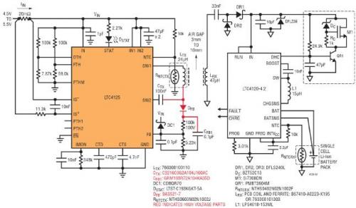
AIR GAP: Air gap
SINGLE CELL Li Ion BATTERY PACK: Single lithium-ion battery pack
Figure 1: In a wireless power system using LTC4120-4.2 as a 400mA single lithium-ion battery charger on the receiver, LTC4125 drives a 24 μ H sends the coil and adopts a 1.3A input current threshold, 119kHz frequency limit, and 41.5 º C sends the coil surface temperature limit
LTC4125 provides all the functions required for a simple, powerful, and secure wireless power transmitter circuit. Especially, the device can adjust the output power according to the receiver load requirements and detect the presence of conductive foreign objects.
As mentioned earlier, the transmitter in the wireless battery charger system needs to generate a strong magnetic field to ensure that the required received power is provided under the worst power transmission conditions. In order to achieve this goal, LTC4125 adopts the proprietary AutoResonant technology of Lingleite Company.
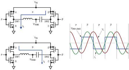
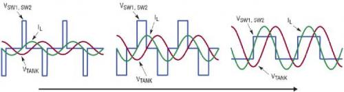
Figure 2: LTC4125 AutoResonant Driver Circuit
The LTC4125 AutoResonant driver circuit ensures that the voltage of each SW pin is always in phase with the current entering that pin. Refer to Figure 2: When the current flows from SW1 to SW2, switches A and C are turned on, switches D and B are turned off, and vice versa. By using this method to lock the driving frequency cycle by cycle, it can ensure that LTC4125 always drives the external LC network at resonant frequency. This always ensures that even when continuously changing variables that affect the resonant frequency of LC resonant circuits, such as temperature and the reflection impedance of nearby receivers, it is no exception.
Using this technology, LTC4125 continuously adjusts the driving frequency of the integrated full bridge switching circuit to match the actual resonant frequency of the series LC network. In this way, LTC4125 can efficiently generate a large amplitude of AC current in the transmitter coil without the need for high DC input voltage or high-precision LC values.
By changing the duty cycle of the full bridge switching circuit, LTC4125 also adjusts the pulse width of the series LC network waveform. By increasing the duty cycle, the LC network in series generates greater current, thus providing greater power to the receiver load.
Figure 3: LTC4125 pulse width scan - as the duty cycle increases, the voltage and current in the Tx coil increase
LTC4125 periodically scans the duty cycle to find the optimal operating point for the receiver load situation. This optimal power point search allows for large air gaps and significant misalignment between coils under all operating conditions, while avoiding overheating of the receiver circuit and excessive electrical pressure. The scanning cycle is easily set with a single external capacitor.
The system shown in Figure 1 can tolerate significant coil misalignment. When the coil is significantly misaligned, LTC4125 can adjust the generated magnetic field strength to ensure that LTC4120 receives all charging current. In the system shown in Figure 1, up to 2W of power can be transmitted over a distance of up to 12mm.
Conductive foreign object detection
Another essential feature of any feasible wireless power transmission circuit is the ability to detect the presence of conductive foreign objects in the magnetic field generated by the transmitting coil. The transmission circuit used to provide the receiver with power exceeding a few hundred milliwatts must be able to detect the presence of conductive foreign objects to prevent the formation of eddy currents in the foreign objects, causing unwanted temperature increases.
The AutoResonant architecture of LTC4125 allows the IC to detect the presence of conductive foreign objects in a unique way. Conductive foreign objects can reduce the effective inductance value in a series LC network. This causes the AutoResonant driver to increase the driving frequency of integrated full bridge circuits.
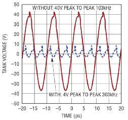
Figure 4: Frequency comparison of LC resonant circuit voltage of LTC4125 transmitter with and without conductive foreign objects
TANK VOLTAGE: Resonant circuit voltage
WithOUT: 40V PEAK TO PEAK 103kHz: No conductive foreign object: 40V peak to peak, 103kHz
With: 4V PEAK TO PEAK 303kHz: Conductive foreign body: 4V peak to peak, 303kHz
TIME: Time
The graph shown in Figure 4 compares the frequency of the voltage generated by the transmitting coil with and without conductive foreign objects.
LTC4125 sets a frequency limit through a resistive voltage divider, reducing the drive pulse width to zero during the period when the AutoResonant drive exceeds this frequency limit. When LTC4125 detects the presence of conductive foreign objects, it stops transmitting power in this way.
Please note that by using this frequency shift phenomenon to detect the presence of conductive foreign objects, a trade-off can be made directly between the detection sensitivity and the component tolerance of the resonant capacitor (C) and the sending coil inductance (L). For a typical initial tolerance of 5% for each L and C value, this frequency limit can be set to be 10% higher than the natural frequency formed by the expected typical LC value to achieve reasonable sensitivity for foreign object detection and reliable transmitter circuit design. However, stricter 1% tolerance components can also be used, while the frequency limit is set to only 3% higher than the expected typical natural frequency to achieve higher detection sensitivity while still maintaining the reliability and robustness of the design.
Flexibility and performance of power fluctuations
By simply changing the values of resistors and capacitors, the same application circuit can be paired with different receiver ICs to achieve higher wattage charging.
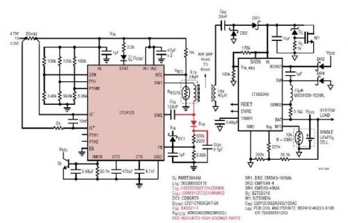
Figure 5: In this wireless power transmission system, LTC4125 drives 24 at a frequency of 103kHz μ H sending coil, with a frequency limit of 119kHz and a surface temperature limit of 41.5 º C. At the receiver end, LT3652HV is used as a 1A single LiFePO4 (3.6V floating voltage) battery charger
AIR GAP: Air gap
SYSTEM LOAD: System load
SINGLE LiFePO4 CELL: Single LiFePO4 battery
Due to the use of a high-efficiency full bridge driver in the sending circuit and a high-efficiency step-down switch topology in the receiving circuit, an overall system efficiency of up to 70% can be achieved. The overall system efficiency is calculated using the DC input of the sending circuit and the battery output of the receiving circuit. Please note that the quality factor of the two coils and their coupling are equally important for the overall efficiency of the system and for the rest of the circuit.
All of these functions of LTC4125 can be achieved without any direct communication between the transmitter and receiver coils. In this way, simple application design can be carried out, covering various power requirements up to 5W and many different actual coil arrangements.
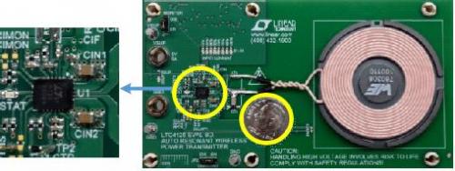
Figure 6: Typical and complete wireless power transmitter circuit board using LTC4125
Figure 6 shows that the overall size of a typical LTC4125 application circuit is very small and simple. As mentioned earlier, most functions can be customized through external resistors or capacitors.
conclusion
LTC4125 is a powerful new type of IC that provides all the functions required to form a safe, simple, and efficient wireless power transmitter. AutoResonant technology, optimal power search, and frequency based conductive foreign object detection reduce the design burden of a fully functional wireless power transmitter with excellent distance and misalignment tolerance. In terms of reliable wireless power transmitter design, LTC4125 is a simple and extraordinary choice.
|
Disclaimer: This article is transferred from other platforms and does not represent the views and positions of this site. If there is any infringement or objection, please contact us to delete it. thank you! |


 Business consulting

 13823761625
 Mail me