


Microcontroller for controlling motor controllers
Time:2023-10-12
Views:528
The following schematic excerpt shows the EFM8 and related circuits:
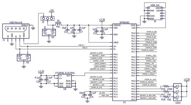 You may have noticed in the diagram that the EFM8 appears to be powered by 5 V from the DC/DC converter. But in reality, EFM8 has an integrated linear regulator that can accept 5 V input and generate 3.3 V voltage for its own use and external circuit use. J2 is a three pin connector that allows users to power the EFM8 with a 5 V voltage provided through a DC/DC converter or USB connection. The latter arrangement is very convenient for initial testing and debugging, as the EFM8 can function normally even if the battery is disconnected or the DC/DC converter cannot operate.
The microcontroller has a fairly accurate integrated oscillator, but I chose to include an external oscillator (U8) in case higher frequency accuracy is needed. The LTC6930 is a "silicon oscillator" - a rather vague term referring to oscillator ICs that do not require piezoelectric components. These devices have certain benefits; You can read more information about silicon oscillators here.
The remaining components are as follows:
J5: A connector that allows us to debug and program the microcontroller using the Silicon Labs USB debugging adapter
LED1: Three universal LEDs (red, green, blue) in one package
FB1: Ferrite magnetic beads that help suppress power noise
D1 and D2: ESD protection diodes for USB signals
J1: USB Micro-B connector, allowing EFM8 to communicate with USB host devices
C3 and C4: Output capacitors for internal reference voltage of EFM8
Various filters/bypass caps for power rails
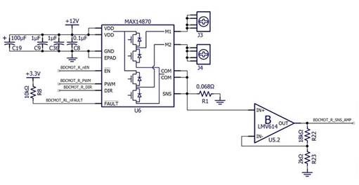
Help for: MAX14870
The board contains two such circuits, as the Tri Track chassis has two tank like tracks, each with a motor. We need to be able to independently control two motors so that we can rotate the robot by changing the speed of one track relative to the other.
I enjoy designing my own circuits, but I also enjoy benefiting from the benefits provided by highly skilled IC designers. Part of engineering humility is accepting the fact that Maxim can design far more than any motor controller I could possibly come up with. Therefore, we have launched the MAX14870, which is a highly integrated, small-sized, and user-friendly device that requires very few external components and only three control signals.
The control interface is simple:
The nEN pin must be driven to a low level to enable motor drive output.
The logic level of the DIR pin controls the direction of rotation of the motor.
As long as the PWM pin is at the logic high level, it will apply driving voltage to the motor. As the name suggests, the speed of the motor can be controlled by applying a pulse width modulation signal to the PWM pin.
Overcurrent conditions or thermal shutdown will drive the nFAULT pin to the logic low level. When there is a problem with the motor control situation, this allows the microcontroller to receive notifications. It is an open drain output, so multiple nFAULT pins can be connected together (although with this arrangement, it is not possible to determine which specific chip is generating a fault condition).
Detection current: V=IR
Let‘s take a moment to understand the situation of detecting resistance R1. Drive the motor by allowing current to flow through one of the high side FETs, motor coil, and low side FETs from the 12 V power supply to the COM pin. This current needs to flow to the grounding node, but we do not need to directly ground the COM pin. If we place a small resistor between the COM pin and ground, the voltage of the COM node will be proportional to the current flowing through the motor coil. In other words, this current detection resistor enables us to monitor the motor driving current.
By adding a detection resistor and connecting the COM node to the SNS pin of MAX14870, we can achieve internal current regulation function. MAX14870 hopes that the voltage of the SNS pin remains below 100 mV; If the voltage starts to become too high, the motor drive current will be affected
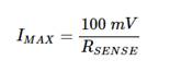
Interrupt as needed to maintain SNS voltage below 100 mV. Therefore, the motor driving current is given by the following equation:
$$I_ {MAX}=frac {100 mV} {R_ {SENSE}}$$
The C-BISCUIT motor control circuit has a 0.068 Ω detection resistor; This means that the motor drive current is limited to approximately 1.47 A. The data sheet of the Tri Track motor indicates that the starting current is approximately 1.5 A, so 1.47 A is a conservative limit that still allows the motor to start normally. But considering that I have no previous experience using this motor or MAX14870, I wouldn‘t be surprised to find that 0.068 Ω is not the value of R SENSE.
It is important to remember that the detection resistor will consume some serious power. This is a place where significant mistakes are easily made, as low-voltage designers usually do not need to carefully consider the rated power of resistors. Although the starting current is higher than the steady-state current, for safety reasons, we assume that the resistor may withstand a current of 1.5 A for a long time. This means that
$$P_ {MAX}=(1.5 A) ^ 2 imes 0.068 Omega=0.153 W$$
I like twice the safety margin, so the rated power of the resistor should be at least 1/4 W. I chose the 1/2 W component because it gave me more confidence that the resistor would not burn out due to the following reason: designer error.
If automatic current regulation is not required, simply ground the SNS pin to disable this function, which (obviously) ensures that the voltage on the SNS never exceeds 100 mV. The MAX14870 still has its universal overcurrent protection function, but only when the current flowing through one of the motor drive lines is greater than about 6 A and the duration exceeds 1? The protection will only activate when s.
Motor current - what EFM8 should know
Due to my decision to add a detection resistor for automatic current regulation, I can also add some additional components to enable the EFM8 microcontroller to collect information about how much current the motor needs under various operating conditions. This is the purpose of the operational amplifier circuit, which is just a gain 10 in-phase amplifier used as an interface circuit between the voltage at both ends of the R SENSE and the EFM8 ADC circuit.
|
Disclaimer: This article is transferred from other platforms and does not represent the views and positions of this site. If there is any infringement or objection, please contact us to delete it. thank you! |


 Business consulting

 13823761625
 Mail me