


How to turn an AC induction motor into a DC motor
Time:2023-10-16
Views:514
The field of high-performance motor control has always been dominated by synchronous DC motors. This group of motors includes brush motors, brushless motors, wound motors, and permanent magnet motors. The simple reason for this dominance is that DC motors are easier to control. This is especially true if the application requires good control of motor torque, speed, or position. The electromechanical model of a DC motor indicates that the motor torque is an approximate linear function of the input current within the limited range. Therefore, using a proportional integral differential (PID) controller to achieve stable performance of a DC motor is a relatively easy task.
In the ‘real design world‘, the process of selecting the type of motor used in the application can be complex. You cannot choose a specific motor solely based on the ease of control. There are many other system related variables that need to be addressed, such as:
How easy is it to maintain the motor?
What happens to the system when the motor malfunctions? (i.e. winding short circuit)
What will happen to the operating environment?
How does the motor cool down?
What is the cost of the motor?
The list of factors to consider can be kept on going
AC induction motors (ACIM) have significant advantages over other types of motors and are typically used when robust speed control solutions are needed. The development of microcontrollers (MCUs) and power electronic devices has made cheap ACIM variable speed control possible. However, using basic control methods cannot match the performance of DC motors. This article will explore the topic of Field Oriented Control (FOC) and how to use it to improve ACIM control using Digital Signal Controllers (DSC). FOC allows you to apply DC control technology to AC motors and eliminate a variable in the next design motor selection process.
The working principle of the motor
When the current flows near the magnetic field, the motor generates mechanical force. Synchronous motors have a magnetic field source. This magnetic field can be provided by permanent magnets or windings powered by a current source. Within the limited range, the torque response of the motor is a linear function of current and magnetic field strength. Linear response makes these motors easy to control in high-performance applications. The PID controller can be used to control the motor current and the generated motor torque. If necessary, an auxiliary PID controller can be used to control position or speed.
So, it seems that our problem has been solved! We will only use synchronous motors with excitation windings or permanent magnets to achieve good control performance. Okay, "wait a minute," you might say. My application requires a high-power motor. I can use a motor with a rotor and stator winding. However, I have to worry about replacing the brushes and maintaining rotor cooling. I can use a brushless motor with a permanent magnet, but the cost of the magnet will make the motor too expensive
AC induction motor
ACIM can indeed provide assistance in this situation. The winding of ACIM is located outside the motor, making it easy to provide cooling. The rotor is a simple steel cage, which is sturdy and durable, and can withstand high temperatures. ACIM has no brushes that will wear out. Okay - so far, everything has been fine. Now, let‘s see how the motor works.
Due to the widespread availability of AC power sources, ACIM usually considers specific line voltages and frequencies when designing. For discussion, let‘s first take a look at the nameplate of a typical ACIM. The parameters displayed on our example nameplate are as follows:
Voltage: 230 VAC
Frequency: 60 Hz
FLA: 1.4A
HP: 1/3
RPM: 3450
In addition, the nameplate also specifies the rated power, working voltage, working frequency, and working speed of the motor. The arrangement of the motor stator winding generates a rotating magnetic field when AC current is energized.
The rotor of ACIM must rotate at a speed lower than the rotating magnetic field. The difference between field speed and rotor speed is called slip. The slip rate can be expressed as a ratio or frequency, but considering the slip frequency can be helpful. For this example motor, the rotational field speed is 60 revolutions per second, which is 3600 RPM. However, you will notice that the nameplate RPM under load is only 3450 RPM, or 57.5 rev/s. Therefore, the slip frequency is 60 Hz – 57.5 Hz, or 2.5 Hz.
In this example, you can consider the 2.5 Hz slip frequency as an AC power source, providing energy to the rotor through transformer coupling. The rotor is energized by alternating current, generating a rotor magnetic field that generates torque for the motor. ACIM slip allows the motor to self regulate its speed to a certain extent. As the motor load increases, the rotor speed will decrease. Then the slip frequency will increase, thereby increasing the rotor current and motor torque.
Variable speed ACIM control
By changing the frequency and voltage provided to the motor, ACIM can operate at different speeds and torque levels. Assuming you want to run our example motor at 1/2 of the rated speed. To achieve this, you can reduce the input frequency of the motor by 1/2, which is 30 Hz. If we want the motor to run at 1/4 speed, the frequency will be reduced to 15 Hz.
You also need to maintain a relatively constant stator magnetic field by keeping the stator current constant. ACIM motors are inductive motors, and the stator current increases with a decrease in input frequency. Therefore, when the frequency decreases, it is also necessary to proportionally reduce the input voltage. A constant V/Hz curve is typically used to provide variable speed operation of ACIM. The V/Hz constant of our example motor can be calculated by dividing the operating frequency by the operating voltage.
K=Voltage/Hz=230/60=3.83
Now, for a given input frequency selection, we can calculate the required driving voltage for that input frequency:
Voltage=K * Frequency
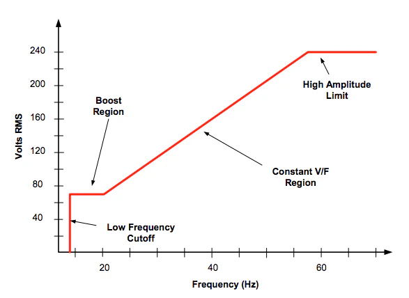
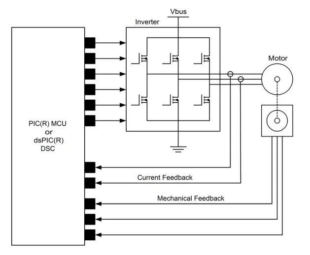
Figure 1 Typical V/Hz Curve for Variable Speed ACIM Applications
The result is called the "V Hz" curve, which can be plotted as shown in Figure 1. There is no fixed rule indicating that the driving voltage must maintain a fixed linear relationship with frequency. In fact, the shape of the V/Hz curve often changes within a specific frequency range to optimize driving performance within a specific speed range. For example, the contour shape shown in Figure 1 has been adjusted to provide higher voltage in the low-frequency range. When the motor starts from a stationary state, this modification can increase the motor torque to help overcome load friction and inertia. Within the mechanical limit range of the motor, you can also increase the drive frequency above the nameplate value to achieve higher speeds. However, the available voltage may be limited, so the motor torque will also be lower.
For applications that do not require frequent speed or load changes, the V/Hz method of controlling ACIM is effective. This is especially true when the control circuit is used to regulate speed or motor current. Figure 2 shows a typical system block diagram that can be used for V/Hz applications. The MCU has a dedicated PWM peripheral to drive the 6-transistor inverter circuit. MCU measures the frequency of the motor tachometer, calculates speed error, and uses PID control loop to generate drive requirements.
Use the V/Hz curve to convert the driving demand into the required voltage and frequency., The PWM modulation code changes the duty cycle over time to generate a sinusoidal driving signal with appropriate amplitude and frequency.
|
Disclaimer: This article is transferred from other platforms and does not represent the views and positions of this site. If there is any infringement or objection, please contact us to delete it. thank you! |


 Business consulting

 13823761625
 Mail me