


Summary of Ultra Full BLDC Motor Control

Many different control algorithms are used to provide control for BLDC motors. A typical approach is to use power transistors as linear regulators to control motor voltage. This method is not practical when driving high-power motors. High power motors must adopt PWM control and require a microcontroller to provide starting and control functions. Many different control algorithms are used to provide control for BLDC motors. A typical approach is to use power transistors as linear regulators to control motor voltage. This method is not practical when driving high-power motors. High power motors must adopt PWM control and require a microcontroller to provide starting and control functions.


The trapezoidal rectifier commutation is not sufficient to provide balanced and accurate control of brushless DC motors. This is mainly because the torque generated in a three-phase brushless motor with a legitimate wave back electromotive force is defined by the following equation:
If the phase current is sinusoidal: IR=I0Sino; IS=I0Sin (+120o); IT=I0Sin (+240o)


1. Scalar control
Scalar control (or V/Hz control) is a simple method of controlling the speed of a command motor. The steady-state model of the instruction motor is mainly used to obtain technology, so transient performance is impossible to achieve. The system does not have a current loop. In order to control the motor, the three-phase power supply only changes in amplitude and frequency.
2. Vector control or magnetic field oriented control
The torque in an electric motor varies with the function of the stator and rotor magnetic fields, and reaches its peak when the two magnetic fields are orthogonal to each other. In scalar based control, the angle between two magnetic fields changes significantly.
Vector control attempts to create orthogonal relationships again in AC motors. In order to control torque, each generates current from the generated magnetic flux to achieve the responsiveness of the DC machine.
The vector control of an AC command motor is similar to the control of a separate excitation DC motor. In a DC motor, the magnetic field energy generated by the excitation current IF Φ F and the armature flux generated by the armature current IA Φ Orthogonal A. These magnetic fields are decoupled and stable with each other. Therefore, when the armature current is controlled to control torque, the magnetic field energy remains unaffected and faster transient response is achieved.
The field oriented control (FOC) of three-phase AC motors includes imitating the operation of DC motors. All controlled variables are converted to DC instead of AC through mathematical transformation. Its goal is to independently control torque and magnetic flux.
There are two methods for Field Oriented Control (FOC):
Direct FOC: The direction of the rotor flux angle is directly calculated through a flux observer.
Indirect FOC: The direction of the rotor flux angle is indirectly obtained by estimating or measuring the rotor speed and slip.
Vector control requires understanding the position of rotor magnetic flux and the ability to use knowledge of terminal current and voltage (using the dynamic model of AC induction motors) to calculate through advanced algorithms. However, from an implementation perspective, the demand for computing resources is crucial.
Different methods can be used to implement vector control algorithms. Feedforward technology, model estimation, and adaptive control techniques can all be used to enhance response and stability.
3. Vector control of AC motors: in-depth understanding
The core of vector control algorithm is two important transformations: Clark transformation, Park transformation, and their inverse operations. By using Clark and Park transformations, the rotor current can be controlled to the rotor region. This allows a rotor control system to determine the voltage that should be supplied to the rotor to maximize torque under dynamically changing loads.
Clark transformation: Clark mathematical transformation modifies a three-phase system into two coordinate systems:

Among them, Ia and Ib are components of the orthogonal reference plane, while Io is the unimportant homoplanar part

Figure 5: Relationship between three-phase rotor current and rotational reference frame

4. Park transformation: Park mathematical transformation converts a bidirectional static system into a rotational system vector
two-phase α,β The frame representation is calculated through Clarke transformation and then input to the vector rotation module, where it rotates the angle θ, To correspond to the d, q frames of the energy attached to the rotor. According to the above formula, the angle is achieved θ Conversion of.
The Basic Structure of Field Oriented Vector Control for AC Motors
The Clarke transformation uses three-phase currents IA, IB, and IC, where the currents of IA and IB in the fixed coordinate stator phase are transformed into Isd and Isq, becoming elements in Park transformation d and q. The current Isd, Isq, and instantaneous flow angle calculated through the motor flux model θ Used to calculate the electric torque of AC induction motors.

Figure 6: Basic principle of vector controlled AC motor
These exported values are compared with the reference values and updated by the PI controller.

Table 1: Comparison of Scalar Control and Vector Control for Electric Motors
An inherent advantage of vector based motor control is that it can use the same principle to select suitable mathematical models to control various types of AC, PM-AC, or BLDC motors separately.
Vector Control of BLDC Motors
BLDC motors are the main choice for field oriented vector control. Brushless motors using FOC can achieve higher efficiency, with a maximum efficiency of 95%, and are also very efficient for motors at high speeds.
1. Stepper motor control
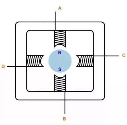
Figure 7
The stepper motor control usually adopts bidirectional driving current, and the motor stepping is achieved by sequentially switching the windings. Usually, this stepper motor has three driving sequences:
① Single phase full step drive:
In this mode, the windings are energized in the following order, AB/CD/BA/DC (BA indicates that the energization of winding AB is in the opposite direction). This sequence is called single-phase full step mode, or wave drive mode. At any one time, only one phase is energized.
② Dual phase full step drive:
In this mode, the two phases are energized together, so the rotor is always between the two poles. This mode is called two-phase full step. This mode is the normal driving sequence of the bipolar motor and can output the maximum torque.
③ Half step mode:
This mode combines single-phase and two-phase stepping for power up: single-phase power up, then two-phase power up, and then single-phase power up... Therefore, the motor operates in half step increments. This mode is called half stepping mode. The effective step angle of each excitation of the motor is reduced by half, and the output torque is also low.
The above three modes can be used for reverse rotation (counterclockwise direction), but not if the order is opposite.
Usually, stepper motors have multiple poles to reduce step angle, but the number of windings and driving sequence remain unchanged.
2. General DC Motor Control Algorithm
Speed control for general motors, especially motors using two types of circuits:
Phase angle control
PWM chopping control
① Phase angle control
Phase angle control is the simplest method for general motor speed control. Control the speed by adjusting the arc angle of TRIAC points. Phase angle control is a very economical solution, but it is not very efficient and prone to electromagnetic interference (EMI).

Figure 8: Phase angle control of general motors
Figure 8 shows the mechanism of phase angle control, which is a typical application of TRIAC speed control. The phase shift of the TRIAC gate pulse generates efficient voltage, resulting in different motor speeds. A zero crossing cross detection circuit is used to establish a timing reference to delay the gate pulse.
② PWM chopping control
PWM control is a more advanced solution for general motor speed control. In this solution, the power MOSFET or IGBT is connected to the high-frequency rectified AC line voltage, thereby generating a voltage that varies over time for the motor.

Figure 9: PWM Chopping Control for General Motors
The switching frequency range is generally 10-20KHz to eliminate noise. This universal motor control method can achieve better current control and better EMI performance, resulting in higher efficiency.
|
Disclaimer: This article is transferred from other platforms and does not represent the views and positions of this site. If there is any infringement or objection, please contact us to delete it. thank you! |


 Business consulting

 13823761625
 Mail me