


Selection of magnetic beads
Time:2023-10-26
Views:520
The Physical Model of Magnetic Beads
Ferrite Beads are a rapidly developing anti-interference component that is cheap, easy to use, and has a significant effect on filtering high-frequency noise. As long as the wire passes through it in the circuit. When current passes through a wire, ferrite has almost no impedance to low-frequency currents, while it has a significant attenuation effect on higher frequency currents. The high-frequency current is dissipated in the form of heat, and its equivalent circuit is a series connection of an inductor and a resistor, with the values of both components proportional to the length of the magnetic bead. There are many types of magnetic beads, and manufacturers should provide technical specifications, especially the impedance frequency curve of the magnetic beads. Some magnetic beads have multiple holes, and using wires to pass through them can increase the impedance of the component (the square of the number of times the magnetic beads pass through). However, the increased noise suppression ability at high frequencies cannot be as much as expected, and using multiple magnetic beads in series would be better.
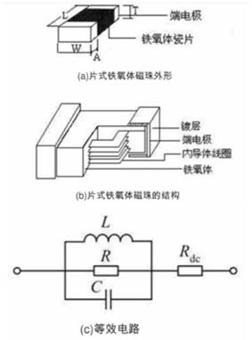
Ferrite is a magnetic material that undergoes magnetic saturation due to excessive current flow, resulting in a sharp decrease in permeability. Large current filtering should use specially designed magnetic beads in structure, and attention should also be paid to their heat dissipation measures. Ferrite magnetic beads can not only be used to filter high-frequency noise in power circuits (can be used for DC and AC output), but also can be widely used in other circuits, and their volume can be made very small. Especially in digital circuits, pulse signals contain high-frequency harmonics, which are the main source of high-frequency radiation in the circuit. Therefore, they can play the role of magnetic beads in such situations. Ferrite magnetic beads are also widely used for noise filtering in signal cables.

Magnetic beads are mainly used to suppress EMI differential mode noise, with a small DC resistance (DCR) and a high high-frequency AC impedance. The common 600 Ω refers to the AC impedance value measured by magnetic beads at a signal frequency of 100MHz. According to different application scenarios, magnetic beads can be divided into ordinary type, high current type, and peak type.
(1) Ordinary magnetic beads. Mainly used in scenarios with low current (less than 600mA) and no special requirements. The DC resistance of ordinary magnetic beads generally does not exceed 1 Ω, and the AC impedance range is generally between a few ohms to several thousand ohms. Its main function is to suppress and absorb electromagnetic interference and radio frequency interference.
(2) High current type magnetic beads. Mainly used in high current scenarios, it is necessary to strictly limit the DC resistance. The DC resistance generally does not exceed 0.1 Ω, and the AC impedance is also smaller than that of ordinary magnetic beads.
(3) Peak shaped magnetic beads. Mainly used to attenuate signals within a specific frequency range and achieve frequency selection function. Its AC impedance is high in a certain frequency range and low in other frequency ranges, exhibiting band resistance characteristics.
The difference between magnetic beads and inductors
1. Inductors are energy storage components, while magnetic beads are energy conversion (consumption) devices. Both inductance and magnetic beads can be used for filtering, but the mechanism is different. Inductive filtering converts electrical energy into magnetic energy, which affects the circuit in two ways: one is to convert it back into electrical energy, manifested as noise; One way is to radiate outward, manifested as EMI (electromagnetic interference). Magnetic beads convert electrical energy into thermal energy and do not cause secondary interference to the circuit.
2. Inductors have good filtering performance in the low frequency range, but their filtering performance is poor in the frequency range above 50MHz; The magnetic bead can fully utilize high-frequency noise by utilizing its resistance component and convert it into thermal energy to completely eliminate high-frequency noise.
3. From the perspective of EMC (electromagnetic compatibility), magnetic beads have excellent radiation resistance due to their ability to convert high-frequency noise into thermal energy. They are commonly used as anti EMI devices for filtering user interface signal lines and power filtering of high-speed clock devices on a single board.
4. When a low-pass filter is composed of an inductor and a capacitor, as both are energy storage devices, the combination of the two may cause self-excitation; Magnetic beads are energy consuming devices that do not self excite when working in conjunction with capacitors.
Main characteristic parameters of magnetic bead device
1. DC Resistance (mohm): The resistance value of this magnetic bead when DC current passes through it.
2. Rated Current (mA): Indicates the maximum allowable current of the magnetic bead during normal operation.
3. Impedance [Z] @ 100MHz (ohm): This refers to the AC impedance.
4. Impedance frequency characteristic: describes the curve of impedance value changing with frequency.
5. Resistance frequency characteristic: describes the curve of resistance value changing with frequency
6. Inductive reactance frequency characteristic: describes the curve of inductive reactance changing with frequency.
The following figure shows the characteristic parameters and frequency characteristic curve of a certain manufacturer‘s magnetic beads:
Selection of magnetic beads
The selection of magnetic beads requires consideration of both noise interference and current flow.
(1) The frequency and intensity of noise interference need to be considered. Different types of magnetic beads have different frequency impedance curves. When selecting a magnetic bead with a higher impedance corresponding to the noise center frequency, it is necessary to choose one to better suppress noise. The greater the noise interference, it is necessary to choose magnetic beads with higher impedance. However, high impedance magnetic beads can also cause significant attenuation of useful signals, so the higher the impedance, the better. Therefore, it is necessary to comprehensively consider the signal-to-noise ratio. At present, there is no clear calculation formula and selection criteria, and selection needs to be based on actual effects. Generally, magnetic beads with AC impedance between 120 Ω and 600 Ω are commonly used. For example, if a noise of 100MHz and 300mVpp is required to reach a level of 50mVpp after passing through magnetic beads, assuming a load of 45 Ω, then 225 Ω @ 100MHz, DCR, should be selected
(2) The rated current needs to be considered in terms of current flow. Magnetic beads with higher DC resistance generally have lower rated current. The selection needs to be based on the actual situation. For example, the output voltage of the system power supply is 3.3V, the rated current required for the power input of the load module is 300mA, and the input voltage required for the input power of the load module cannot be lower than 3.0V. The power input pins of this load module need to choose magnetic beads with a DC resistance less than 1 Ω, and then consider the derating design. Generally, 0.5 Ω magnetic beads are chosen.
Therefore, when selecting magnetic beads, the following steps can be followed.
(1) Firstly, it is necessary to determine the frequency range of noise that needs to be filtered out, and then select the appropriate AC impedance within this frequency range (the approximate impedance range can be obtained through simulation, and the simulation model can be consulted with the manufacturer).
(2) Determine the maximum current that the circuit passes through. The current flowing through the circuit determines the rated current of the magnetic bead. Once the rated current is determined, the DCR range of the magnetic bead can be calculated based on the voltage range required by the subsequent circuit.
(3) Select encapsulation. Packaging can be selected based on the actual layout and structure of the board. However, it should be noted that the impedance of the magnetic bead differs from the impedance on the specification after applying voltage. To select magnetic beads correctly, the following points must be noted.
① What is the frequency range of unnecessary signals?
② What is the source of noise?
③ How much noise attenuation is required?
④ What are the environmental conditions (temperature, DC voltage, structural strength)?
⑤ What are the circuit and load impedances?
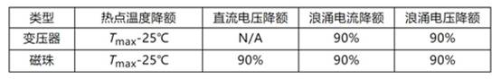
Finally, when selecting magnetic beads, it is also necessary to pay attention to the use of derating. The derating standards for magnetic devices are shown in the table.
Derating standards for magnetic devices
|
Disclaimer: This article is transferred from other platforms and does not represent the views and positions of this site. If there is any infringement or objection, please contact us to delete it. thank you! |


 Business consulting

 13823761625
 Mail me