


Using DAC to output sine waves
Time:2023-10-30
Views:543
This application note introduces how to use a digital to analog converter to generate sinusoidal waveform output. This document also describes the specifications, operational check conditions, hardware, as well as software and example code for using DAC, data transmission controller, and event link controller in RL78/G14 group MCU.
specifications
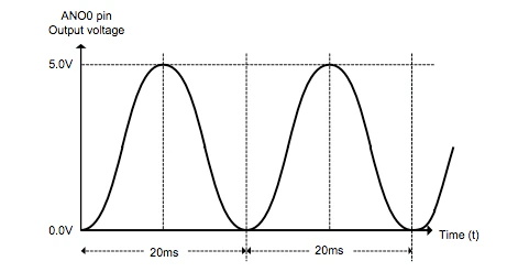
Use a D/A converter to output analog voltage from the ANO0 pin. The analog voltage output starts at 0.0 V. Output level every 200? S variation, sinusoidal waveform of 50 Hz (1 cycle: 20 ms)
Sine wave, DA converter, analog voltage
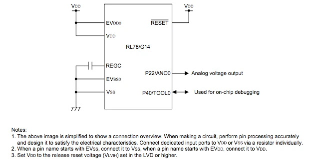
Figure 2 shows the hardware configuration used in this document.
Software: Operational Overview
Use DAC0 to output analog voltage from the ANO0 pin. After the DAC0 conversion operation is enabled, the analog output voltage immediately reaches 0.0 V. Use TAU0 channel 0 (TAU00) in interval timer mode, and every 200? Generate interrupt. Start the analog output voltage conversion using ELC‘s DAC0 by terminating the interrupt through TAU00 counting. Simultaneously start DTC and transfer the values stored in the D/A conversion value table to the D/A conversion value setting register 0 (DACS0).
D/A conversion table:
This table is available every 200? Switch the value of the analog output voltage from 0.0 V to 5.0 V, and output a sine waveform of 50 Hz every 100 cycles when the VDD is 5.0 V.
|
Disclaimer: This article is transferred from other platforms and does not represent the views and positions of this site. If there is any infringement or objection, please contact us to delete it. thank you! |


 Business consulting

 13823761625
 Mail me