


Simplified lithium-ion battery charger testing
Time:2023-11-06
Views:514
Due to the fact that the charging process of lithium-ion batteries may take an hour or more, testing lithium-ion battery chargers using their natural load (i.e. battery) is both time-consuming and inconvenient. This application note introduces a simple circuit for simulating the behavior of Li+batteries, providing a more convenient method for testing Li+battery chargers than using real batteries.

introduce
Lithium ion (Li+) batteries are more fragile than other chemical batteries and are difficult to tolerate abuse. Therefore, lithium-ion battery chargers are complex circuits that require high-precision current and voltage settings. If these accuracy requirements are not met, the charger may not be able to fully charge the battery, significantly shorten battery life, or otherwise reduce battery performance.
Considering the requirements for Li+chargers, it is crucial to thoroughly test the charger design and gradually complete its entire scope of work. However, in both laboratory and production environments, testing lithium-ion chargers with their natural load (i.e. lithium-ion batteries) can be time-consuming and impractical. To simplify the process, this article proposes a battery simulation circuit for accelerating and truly testing lithium-ion battery chargers without actual batteries.
CC-CV charging
The Li+battery charging process requires intermediate precision constant current (CC) charging in the stage, and transitioning to high-precision constant voltage (CV) charging in the second stage.
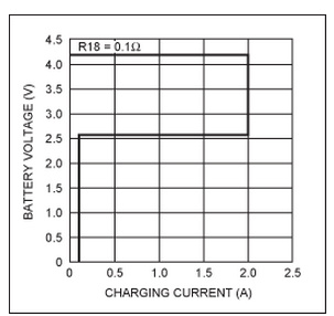
VI characteristics of modern CC-CV integrated circuits (MAX1737) for Li+battery chargers. This type of IC is used for all lithium-ion battery chargers in consumer products. The CC (between 2.6V and 4.2V battery voltage) and CV (4.2V) areas are clearly displayed.
Areas below 2.6V require different charging techniques. If you attempt to charge a battery with a discharge voltage below 2.6V, the charger will apply a low charging current ("regulating current") until the battery reaches the 2.6V level. This is a necessary safety mechanism for the behavior of lithium-ion batteries during excessive discharge. Forcing a fast charging current when VBATT<2.6V may cause the battery to enter an irreversible short-circuit state.
The transition point from CC to CV stage has a critical tolerance of ± 40mV. The reason for the narrower tolerance is that lower CVs do not allow the battery to be fully charged, while higher CVs shorten its service life.
The termination of the charging process involves sensing that the battery is fully charged and the charger must be disconnected or turned off. This is achieved by detecting the point at which the charging current decreases to a small portion (usually<10%) of the so-called fast charging or charging current during the CV stage.
Li+charger test parameters
The design of Li+battery chargers typically consists of two basic building blocks: a digital module (control state machine) and an analog module, consisting of a well regulated current/voltage power supply with a reference (better than 1%). Compared to simply verifying some current or voltage values, conducting a complete test of Li+charger products (not just ICs) is a more complex and time-consuming task.
The test should gradually allow the charger to go through its entire operating range: through the CC stage, until the transition from CC to CV, and until the charging is terminated. Recall that the actual condition for such tests is to use the natural load of the charger: Li+battery. However, testing lithium-ion chargers using lithium-ion batteries is very time-consuming, as the charging process may take an hour or more. Depending on whether you combine a higher capacity battery with a slow charger, a lower capacity battery with a fast charger, or a charger in between, the testing time varies greatly.
In addition, without damaging the battery, the acceleration speed of the charging process cannot exceed the limit imposed by the battery charging rate (so-called fast charging current). For ordinary batteries used in consumer products, this current is rarely specified to be higher than 1C (the current required to fully discharge the battery within one hour). Therefore, in most cases, the time required to complete the entire cycle with a charger will exceed two hours.
If repeated testing is required, the battery must be fully discharged - this process is only slightly shorter than charging. Alternatively, you must have a continuously discharging battery.
Another method of using real batteries for load testing is to use simulated but real loads to test the charger. This simulation should verify the DC response and dynamic stability of the circuit. However, battery simulation is difficult to achieve with the standard load used in power testing. Unlike most bench loads used for power testing, batteries do not act as resistors or constant current absorbers. As mentioned above, the test must also gradually allow the charger to complete its entire working range. The Li+charger test circuit outlined below meets all of these requirements.
Select battery model load
Let‘s digress and discuss two modeling methods that should be considered but will be discarded later.
One method of modeling battery loads is to use a voltage source that can provide current (discharge) and absorb current (charge), and connect it in series with a resistor representing the internal resistance of the battery. Due to the need to limit the voltage termination and charging current of lithium-ion batteries, all lithium-ion chargers today are actually regulated power converters.
In addition, since the stability of the regulated power converter (charger) depends on the dynamic characteristics of the connected load (battery), you must choose a load with very similar characteristics to the model. Otherwise, the test may only verify the VI limitations of the charger itself.
If testing is a sexual task and a simple battery model meets the testing requirements, using a parallel regulator with series resistors to simulate the internal resistance of the battery may be sufficient. This method also has the advantage of being powered by the charger itself.
However, stricter testing requires more complex models. This model uses an internal voltage source, whose value is a function of the total amount of electricity provided to the battery during the charging process.
The voltage between battery terminals charged with a constant current varies continuously with a positive slope. This behavior is caused by the gradual reduction of depolarized ions accumulated around the battery cathode during discharge and other chemical processes inside the battery. Therefore, the working point of the charger depends on the length of time it has been connected to the battery and the past history of the battery. It is more difficult to set up a load for simulating this more complex model using general instruments in most electronic laboratories.
When it is necessary to frequently test the charging circuit or to characterize the circuit performance in detail, closely simulating the circuit of a charging battery is a useful laboratory accessory. The simulation should continuously scan all possible DC operating points of the charger. The circuit should also display the results so that the operator can identify problems, burrs, and oscillations. If the simulator provides battery voltage and signal output, these results can be directly presented as oscilloscope lenses.
This test can be accelerated (from a few hours to tens of seconds) and repeated multiple times as needed, making it much more convenient than testing with real batteries. However, accelerated testing is not sufficient to determine the thermal impact of power stress on the charger circuit. Therefore, you may need to conduct additional tests over a longer period of time to adapt to the thermal time constant in the charger power supply and regulation circuit.
The circuit in Figure 2 simulates a single lithium-ion battery. The termination voltage and fast charging current generated during the CC phase of the charger are controlled by the settings on the charger. When the simulator is initialized to a fully discharged state, the internal battery voltage is set to 3V, but this voltage can be increased to 4.3V to test the overcharge state. 3V initialization is a typical case of a low battery shutdown circuit used to terminate the discharge of Li+batteries. This design is designed to be used in conjunction with a standard CC-CV Li+battery charger to terminate charging at 4.2V. This design can be easily adjusted to accommodate non-standard levels of termination voltage and complete discharge voltage.
The tested charger drives the simulator with a charging current of up to 3A, but is limited by the dissipation of power transistors. The increase in battery voltage simulated by the circuit in Figure 2 is a function of all charging currents integrated by the circuit when the simulator is set to a fully discharged state.
Based on the displayed value and 1A charging current, the integration time constant allows the simulator to reach the 4.2V limit of the charger within six to seven seconds. The simulation of current range, internal resistance, charging termination voltage, and complete discharge voltage is based on the specifications of a typical Li+battery (in this case, SonyUS18650G3). The simulated battery voltage does not include the simulation of environmental temperature effects.
The parallel voltage regulator is designed around a MAX8515 parallel voltage regulator and a pair of bipolar power transistors. The choice of this voltage regulator is due to the accuracy of its internal voltage reference. The high current TIP35 transistor is connected to a heat sink that can dissipate approximately 25W of power.
Half of the MAX4163 dual operational amplifier integrates charging current, while the other half amplifies the current measurement signal and performs level conversion. The high PSRR and rail to rail input and output range of the operational amplifier simplify the circuit design of these two functions. Please note that the 0.100 Ω current detection resistor connected in series with the positive pole of the battery simulator is also used as the internal resistance of the battery.
When running in a system with automatic test data collection function, the simulator can be reset to a fully discharged state through external signals. Alternatively, when manually operating the test settings, they can be reset through a button.
The single pole single throw switch allows you to choose two operating modes for the simulator. In position A, the switch operates as an integrated charge simulator, as described above. At position B, it assumes the set output voltage and absorbs current as needed for on-site testing of the charger at a fixed DC operating point. To achieve this, the "set" voltage can be manually adjusted between 2.75V and 5.75V through a 50k Ω variable resistor. These set voltage values refer to the internal current source. The actual measured voltage (VBATT) between the emulator terminals is equal to the set voltage plus the voltage drop caused by the current flowing through the emulator‘s internal resistance (0.100 Ω resistance). All the power required to operate the simulator comes from the output of the battery charger.
|
Disclaimer: This article is transferred from other platforms and does not represent the views and positions of this site. If there is any infringement or objection, please contact us to delete it. thank you! |


 Business consulting

 13823761625
 Mail me