


Introduction to ACM6763 24V 5A three-phase non-inductive BLDC brushless DC motor driver chip
Time:2023-12-29
Views:360
brief introduction
ACM6763 is a three-phase brushless DC motor driver chip that integrates an inductive three-phase brushless motor driver algorithm, a phase current detection circuit, a gate driver circuit, and a power MOSFET Supports a maximum phase current of 5A
The high integration and streamlined peripheral of ACM6763 are particularly suitable for the application scenarios of three-phase brushless motor drivers with high power density, small size, and high noise requirements
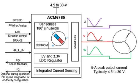
ACM6763 supports 180 ° sine drive, effectively avoiding electromagnetic interference caused by high-order harmonics. ACM6763 can start, accelerate, and operate at constant speed based on the motor parameters provided by the user. User parameters can be fixed for a long time through burning (hardware mode, internal EEPROM programming) or controlled online through I2C (software mode, parameter initialization or online control through I2C register) ACM6763 supports various speed controls. External PWM duty cycle speed regulation, external analog voltage speed regulation, I2C register speed regulation, and external PWM frequency speed regulation
ACM6763 supports multiple protection mechanisms to protect itself and external motors
function
Working voltage range: 4.5V to 32V Support vehicle mounted 40V load shedding operation ◆
Upper side MOS+lower side MOS: 180m Ω, 5A output current capacity
one hundred and eighty ˚ Sinusoidal drive, low noise
No induction or single Hall operation, no need for external current detection of resistance
Internally integrated 5V and 3.3V LDO
FG pin speed indication
Fault indication
Brake control
-BRAKE pin brake control
-I2C interface: brake command
4 flexible speed control methods
-Specific speed control pin SPEED: accepts external analog voltage speed regulation, PWM duty cycle speed regulation, or external clock speed regulation
-I2C register control speed regulation
Protection function
-Overcurrent protection
-Locked rotor protection
-Overvoltage/undervoltage protection
-Over temperature protection
-Voltage anti backflow (anti overshoot) mechanism
Static current (in standby mode): 150uA, with an I2C speed command (speed configured to zero) and an external SPEED pin voltage of zero
Quiescent current (in sleep mode): 20uA, awakened by increasing external SPEED pin voltage
application
Fan type motor drive, water pump type motor drive, other applications with relatively constant loads, etc
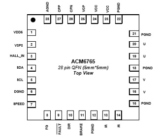
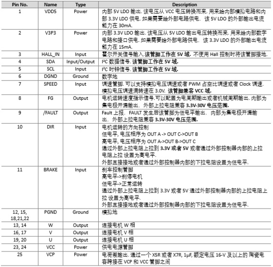
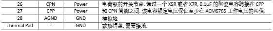
Definition of pins and description of pin functions
Simplified schematic diagram
|
Disclaimer: This article is transferred from other platforms and does not represent the views and positions of this site. If there is any infringement or objection, please contact us to delete it. thank you! |


 Business consulting

 13823761625
 Mail me