


Deep analysis of stepper motors
Time:2023-12-31
Views:322
Stepper motors are widely used in the motor industry due to their excellent performance in speed and position control accuracy. We will conduct in-depth analysis on the architecture and driving mode, working principle, and precautions in application of stepper motors.
.jpg)
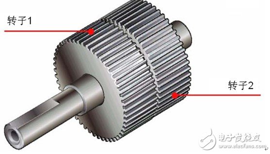 The outer ring of the rotor is composed of 50 small teeth, and the small teeth of rotor 1 and rotor 2 are structurally offset by 1/2 pitch from each other. As a result, the rotor forms 100 small teeth. At present, there are high-resolution types of rotors that can be machined to 100 teeth per rotor, so the high-resolution type of rotor has 200 small teeth. Therefore, mechanically, it can achieve a resolution of half step for ordinary stepper motors (which require electrical subdivision).
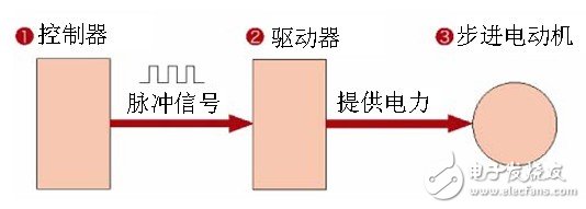
A stepper motor is a special type of motor used for control, which rotates step by step at a fixed angle (known as the "step angle"). Its characteristic is that there is no accumulated error (accuracy of 100%), so it is widely used in various open-loop controls. The operation of a stepper motor requires an electronic device to drive it, which is called a stepper motor driver. It converts the pulse signal emitted by the control system into the angular displacement of the stepper motor. In other words, for each pulse signal sent by the control system, the driver rotates the stepper motor by one step angle. Therefore, the speed of the stepper motor is proportional to the frequency of the pulse signal. Therefore, controlling the frequency of the stepper pulse signal can accurately regulate the speed of the motor; Controlling the number of stepper pulses can accurately locate the target of the motor. The existence of this linear relationship, coupled with the characteristics of stepper motors having only periodic errors and no cumulative errors. It makes it very simple to use stepper motors to control speed, position, and other control fields.
1、 Construction of Stepping Motor (Taking Five Phase Stepping Motor as an Example)
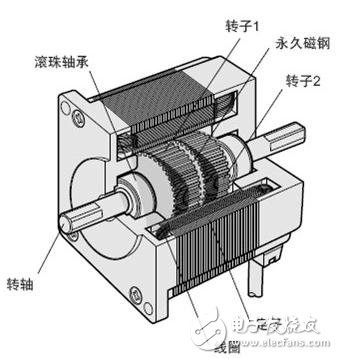
The structure of the stepper motor is shown in the following figure, roughly divided into two parts: stator and rotor. The rotor is composed of rotor 1, rotor 2, and permanent magnet steel.
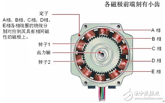
The stator has 10 small toothed magnetic poles, all of which are wound with coils. The magnetic poles at the diagonal positions of the coil are connected to each other, and after the current flows, the coil will be magnetized to the same polarity. For example, after a coil passes through the flow of current, the magnetic poles on the diagonal will assimilate into S or N poles. The two magnetic poles on the diagonal form one phase, and since there are 5 equal phases from A to E, it is called a 5-phase stepper motor.
2、 Working principle of stepper motor
When the current flows through the stator winding, a vector magnetic field is generated in the stator winding. This magnetic field will drive the rotor to rotate by an angle, so that the direction of a pair of magnetic fields in the rotor is consistent with the direction of the magnetic field in the stator. When the vector magnetic field of the stator rotates by an angle. The rotor also rotates at an angle with the magnetic field. For each input of an electrical pulse, the motor rotates one angle and moves forward one step. Its output angular displacement is proportional to the number of input pulses, and the speed is proportional to the pulse frequency. Changing the order in which the windings are energized will cause the motor to reverse. So the rotation of the stepper motor can be controlled by controlling the number and frequency of pulses, as well as the order in which each phase winding of the motor is energized.
3、 Control of stepper motors
There are three basic driving modes for stepper motors: full step, half step, and subdivision. The main difference lies in the control accuracy of the motor coil current (i.e. excitation method). Usually, stepper motors have the characteristic of low-frequency vibration, and the balance of low-speed motor operation can be improved through fine tuning. Below is a detailed introduction for everyone:
2.1. Full step drive
In full step operation, the same type of stepper motor can be equipped with both full/half step drivers and subdivided drivers, but the operating effect is different. The stepper motor driver circularly excites the two coils of the two-phase stepper motor according to the pulse/direction command (i.e., the coil is charged with a set current). Each pulse of this driving method will cause the motor to move by a basic step angle of 1.80 degrees (a standard two-phase motor has a total of 200 step angles per cycle).
2.2. Half step drive
When single-phase excitation occurs, the motor shaft stops at the full step position. After receiving the next pulse, if the driver excites the other phase and keeps it in the original continuous excitation state, the motor shaft will move half a step angle and stop in the middle of two adjacent full step positions. In this way, the two-phase coils are cycled in a single-phase manner, and then the two-phase excitation stepper motor will rotate in a half step manner at 0.90 degrees per pulse. Compared with the whole step method, the half step method has the advantages of twice the accuracy and less vibration during low-speed operation, so the half step mode is generally chosen when using whole/half step drivers in practice.
2.3. Subdivision driven
The subdivision driving mode has two major advantages: minimal low-speed vibration and high positioning accuracy. For stepper applications that sometimes require low-speed operation (i.e. the motor shaft sometimes operates below 60rpm) or require positioning accuracy less than 0.90 degrees, subdivision drives are widely used.
The basic principle is to precisely control the current of the two coils of the motor according to sinusoidal and cosine steps, so that the distance of a step angle is divided into several sub steps to complete. For example, the sixteen subdivision driving method can achieve a running accuracy of 200 * 16=3200 steps per turn (i.e. 0.1125 °) for a stepper motor with 200 standard steps per turn.
4、 Notes in application
4.1. Stepper motors are used in low-speed situations - the speed does not exceed 1000 revolutions per minute (6666PPS at 0.9 degrees), and it is best to use them between 1000-3000PPS (0.9 degrees). They can be operated in this range through a reduction device, resulting in high motor efficiency and low noise.
4.2. It is best not to use the full step state for stepper motors, as there is significant vibration during the full step state.
4.3. For loads with large moments of inertia, a motor with a large base number should be selected.
4.4. When the motor is under high speed or large inertia load, it generally does not start at the working speed, but gradually increases the frequency and speed. Firstly, the motor does not lose step, secondly, it can reduce noise and improve the positioning accuracy of stopping.
4.5. When achieving high precision, mechanical deceleration, increasing motor speed, or using high-precision drivers can be used to solve the problem. 5-phase motors can also be used, but the entire system is more expensive and has fewer manufacturers.
5、 Precautions for testing stepper motors
According to the national standard GB/T 20638-2006, for the testing of stepper motors, we generally need to pay attention to tests such as back electromotive force constant, holding torque, winding temperature rise, torque angle characteristics, pull-out torque, and maximum reverse frequency.
For the testing of the back electromotive force constant, the testing method of a power analyzer can be used to directly obtain the back electromotive force constant on the instrument. For torque testing, for stepper motors with large bases, magnetic particle brakes and motor testing platforms are generally used for testing, while for stepper motors with small bases, a combination of spring scales and ropes is used for testing. The MPT motor testing system currently provides a comprehensive testing plan and system for stepper motors, helping engineers quickly improve the development and design of stepper motors.
|
Disclaimer: This article is transferred from other platforms and does not represent the views and positions of this site. If there is any infringement or objection, please contact us to delete it. thank you! 矽源特科技ChipSourceTek |


 Business consulting

 13823761625
 Mail me