


Introduction to the Construction of High Current H-Bridge Motor Driver Circuit with Driver Chips and MOSFETs
Time:2024-01-11
Views:285
Introduction to the Construction of High Current H-Bridge Motor Driver Circuit with Driver Chips and MOSFETs

 Detailed explanation of high current H-bridge motor drive circuit
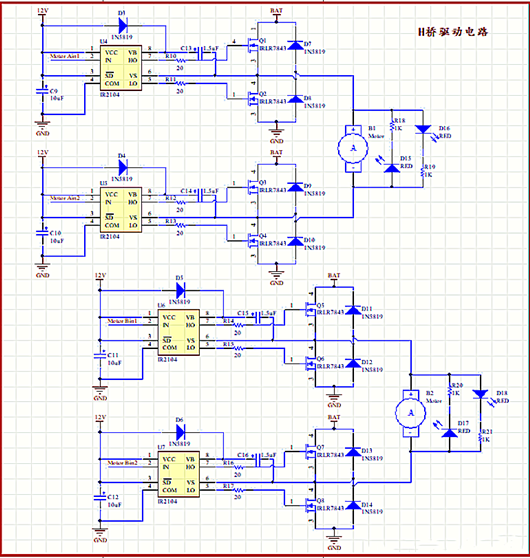
Build a suitable H-bridge motor drive circuit using half bridge/full bridge drive chips and MOSFETs to achieve driving control of high current motors. The motor driver board has two H-bridge circuits that can simultaneously control dual motors. The motor speed and forward/reverse rotation can be controlled through corresponding control signals.
Schematic diagram of high current H-bridge motor drive circuit
PCB 3D diagram
Building an H-bridge driver circuit generally includes two parts: a half bridge/full bridge driver chip and a MOSFET. The current that a self built H-bridge driver can pass through is almost determined by the conduction and drain current of the MOSFET. Therefore, by selecting the appropriate MOS transistor, an H-bridge driving circuit for driving high current motors can be designed.
NMOS transistor
When choosing MOSFETs to build H-bridges, the following parameters should be noted:
1. Leakage current (Id): This current limits the maximum current that can be connected to the motor (usually greater than the current when the motor is locked, otherwise it may burn out the MOS transistor when the motor is locked).
2. Gate source threshold voltage/turn on voltage (Vth): This voltage is the minimum voltage required for the MOS transistor to turn on, and will also determine the selection and design of the subsequent half bridge driver chip (i.e. the output voltage of the chip gate control pin).
3. Leakage source conduction resistance (Rds): This resistance is the internal resistance of the loss between the drain and source when the MOS transistor is conducting, which will determine the amount of heat generated on the MOS transistor when the motor rotates. Therefore, the smaller the resistance, the better.
4. Maximum leakage source voltage (Vds): This voltage is the maximum voltage that MOS transistors can withstand between leakage sources, and must be greater than the motor driving voltage applied to the H-bridge.
Half bridge driver chip
In the H-bridge driver circuit, a total of 4 MOS transistors are required. And the conduction and cutoff of these four MOS transistors require specialized chips for control, that is, half bridge/full bridge drive chips.
The so-called half bridge driver chip refers to a driver chip that can only be used to control two MOS transistors on one side of the H-bridge (one high-end MOS and one low-end MOS). Therefore, when using a half bridge driver chip, two of these chips are needed to control a complete H-bridge.
Correspondingly, the full bridge driver chip can directly control the conduction and cutoff of four MOS transistors, and one chip can complete the control of a complete H-bridge.
|
Disclaimer: This article is transferred from other platforms and does not represent the views and positions of this site. If there is any infringement or objection, please contact us to delete it. thank you! |


 Business consulting

 13823761625
 Mail me