


Analysis of DC bias phenomenon
Time:2024-01-29
Views:251
When constructing multilayer ceramic capacitors (MLCC), electrical engineers usually choose two types of dielectrics based on the application - Class 1, non ferroelectric material dielectrics, such as C0G/NP0; Class 2, ferroelectric material dielectric, such as X5R and X7R. The key difference between them is whether the capacitor still has good stability as the voltage and temperature increase. For Class 1 dielectrics, the capacitance remains stable when a DC voltage is applied and the operating temperature rises; Two types of dielectrics have high dielectric constants (K), but their capacitance values are not very stable under temperature, voltage, frequency changes, and over time.
Although various design changes can be made to increase the capacitance value, such as changing the surface area, number of layers, K value, or distance between two electrode layers, when a DC voltage is applied, the capacitance value of Class 2 dielectrics will eventually sharply decrease. This is due to the existence of a phenomenon called DC bias, which leads to a decrease in the dielectric constant of Class 2 ferroelectric formulas when applying DC voltage.
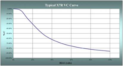
For dielectric materials with higher K values, the impact of DC bias may be more severe, and capacitors may lose up to 90% or even more of their capacitance, as shown in Figure 1.
Figure 1. Voltage variation curve of X7R capacitor
The dielectric strength of a material, which is the voltage that a certain thickness of material can withstand, can also change the effect of DC bias on capacitors. In the United States, dielectric strength is usually measured in volts per mil (1 mil equals 0.001 inches), while in other places it is measured in volts per micrometer, which is determined by the thickness of the dielectric layer. Therefore, different capacitors with the same capacitance and rated voltage may have significant differences in performance due to their different internal structures.
It is worth noting that when the applied voltage is greater than the dielectric strength of the material, sparks will pass through the material, leading to potential ignition or small-scale explosion risks.
A practical case study on how DC bias is generated
If we combine the capacitance change caused by the working voltage with the temperature change, we will find that under specific application temperatures and DC voltage, the capacitance loss of the capacitor will be greater. Taking the MLCC made of a certain X7R material as an example, its capacity value is 0.1 μ F. The rated voltage is 200VDC, with 35 internal layers and a thickness of 1.8 mils (0.0018 inches or 45.72 microns). This means that when operating at 200VDC, the dielectric layer only experiences 111 volts/mils or 4.4 volts/microns. Roughly calculated, VC will be -15%. If the temperature coefficient of the dielectric is ± 15% Δ C. VC is -15% Δ C. So the maximum TVC is+15% -30% Δ C.
The reason for this change is the crystal structure of the two types of materials used - in this case, barium titanate (BaTiO3). When the material reaches Curie temperature or above, it has a cubic crystal structure. However, when the temperature returns to the ambient temperature, polarization occurs due to the change in the structure of the material caused by the decrease in temperature. The occurrence of polarization does not require any external electric field or pressure, which is called spontaneous polarization or ferroelectricity. When a direct current voltage is applied to the material at ambient temperature, spontaneous polarization is connected to the direction of the direct current voltage electric field, and a reversal of spontaneous polarization occurs, resulting in a decrease in capacitance.
Nowadays, even with various design tools to improve capacitance, due to the existence of DC bias, the capacitance of Class 2 dielectrics will still significantly decrease when DC voltage is applied. Therefore, to ensure the long-term reliability of the application, when choosing MLCC, in addition to considering the rated capacity of MLCC, you also need to take into account the impact of DC bias on the components.
|
Disclaimer: This article is transferred from other platforms and does not represent the views and positions of this site. If there is any infringement or objection, please contact us to delete it. thank you! |


 Business consulting

 13823761625
 Mail me