


Accurate design of EMI filters
Time:2024-02-19
Views:208
With the development of electronic technology, electromagnetic compatibility has become a highly concerned and challenging issue for circuit design engineers. Based on years of engineering experience, it is generally believed that the two most important and difficult items to solve in electromagnetic compatibility standards are conducted emission and radiated emission. In order to meet the requirements of conducted emission limitations, electromagnetic interference (EMI) filters are usually used to suppress the conducted noise generated by electronic products. But how to choose an existing filter or design a filter that can meet the needs? The engineer acted very blindly and had to rely on experience to make attempts. Firstly, use a filter based on experience. If it cannot meet the requirements, redesign or replace it with a new filter. Therefore, finding a suitable EMI filter becomes a time-consuming and costly task.
Interference characteristics generated by electronic systems
To solve the problem, the first step is to understand the total interference generated by the electronic system, and how much interference voltage needs to be suppressed to meet the standard requirements? What is common mode interference and differential mode interference? Only by clarifying these interference characteristics can we make requirements based on actual needs.
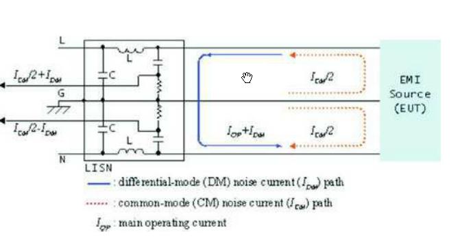
From the current path of the tested object, the interference signal return path may pass through the ground wire or other power grids, as shown in Figure 1. The interference current passing through the ground wire generates common mode interference voltage in the same phase on the power grid. Generate reverse differential mode interference voltage on two power lines through other wires. The path of interference current is shown in Figure 2.
Figure 1: Return path of interference signal
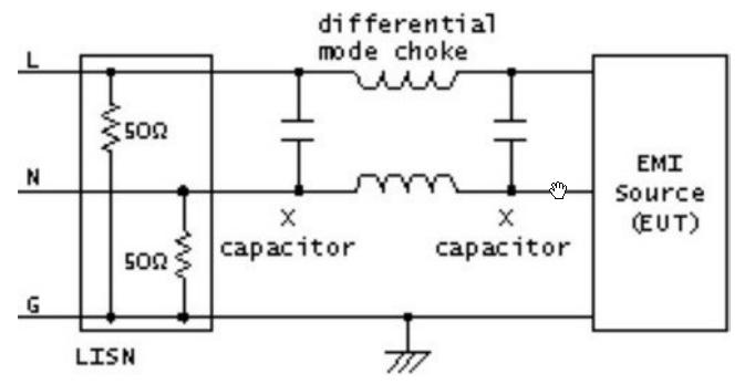
Figure 2a) Differential mode interference filtering and b) Common mode interference filtering
There are usually four techniques for power filtering to suppress interference noise. In practical use, it is often a combination of two or even multiple technologies. They are:
Add capacitance between the positive and negative power lines, i.e. X capacitance;
Add a capacitor, i.e. Y capacitor, between each power cord and ground wire;
Common mode suppression (the suppression coils on two power lines are wound in the same direction);
Differential mode suppression (each power cord has its own suppression coil).
The function of capacitors is to short-circuit high-frequency interference voltage. In addition, when the interference signal frequency is very high, the suppression coil will generate a large AC impedance. Figure 2 shows the structures of two types of filtering, where LISN is a linear impedance stable network used for measurement purposes. If the interference is caused by common mode issues, the X-type capacitor is basically ineffective because the interference voltage on the two lines is the same. Therefore, understanding the types of interference will play an important role in selecting a reasonable circuit structure and provide technical basis for solving problems.
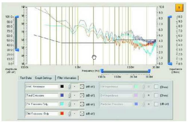
The total interference situation of the equipment can be obtained in the standard electromagnetic compatibility testing laboratory, but the common mode interference and differential mode interference characteristics of the equipment cannot be understood. It is difficult to achieve universal instruments to distinguish common mode or differential mode interference signals in measurement. By using a dedicated conductivity tester, the total interference, common mode interference, and differential mode interference of the equipment can be obtained. The test results are shown in Figure 3.
Figure 3 Total interference, common mode interference, and differential mode interference obtained by traditional testers
Power input impedance characteristics
The filter insertion loss provided by the manufacturer is the performance in a 50W standard impedance system. As is well known, the input impedance of a power supply exhibits discontinuity with frequency variation. The change in impedance leads to significant changes in the insertion loss characteristics of the filter.
As shown in Figure 4, in a 50W system, a 100mH filter provides approximately 18dB of attenuation, but only about 4dB of attenuation in a 500W system. Similarly, for 100nF capacitors; In a 50W system, the attenuation of approximately 23dB at 1MHz decreases to 7dB in a 5W system.
The above example illustrates that selecting a filter with high insertion loss cannot effectively suppress conducted noise due to the influence of the input impedance of the power supply. Therefore, in addition to selecting a suitable filter, designers also need to understand the impedance characteristics, common mode impedance, and differential mode impedance of the power supply. Impedance testing can be carried out using specialized impedance testers or conductivity analyzers. The changes in common mode impedance (a) and differential mode impedance (b) of a filter are shown in Figure 5.
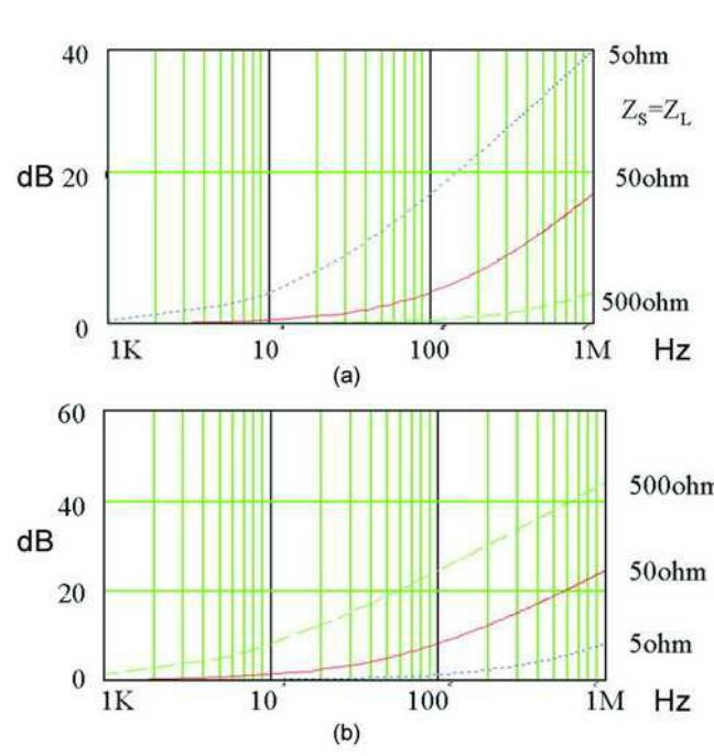
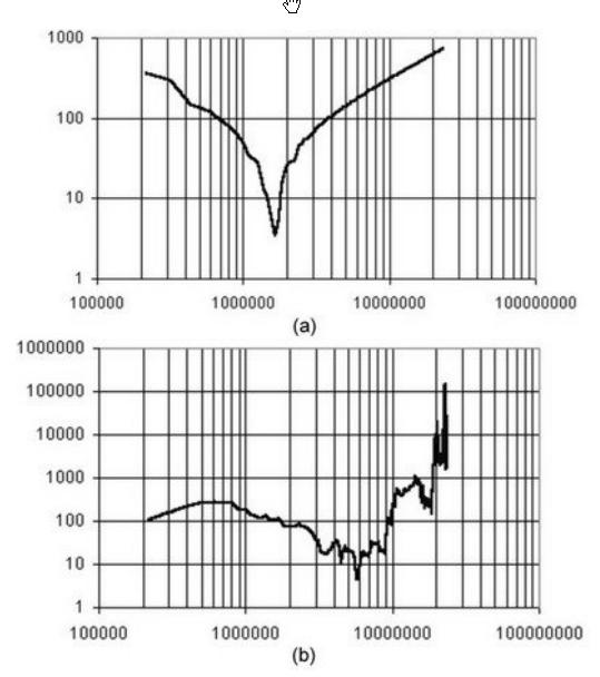
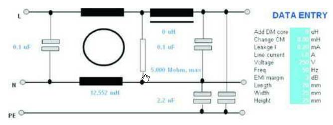
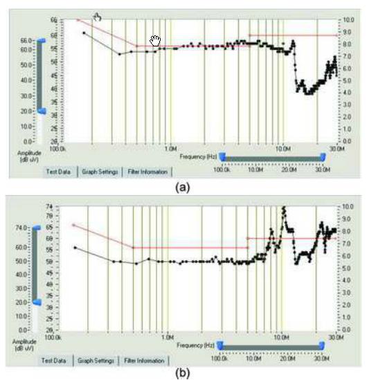
Figure 4a) Attenuation of 100uh inductor b) Attenuation of 100nF capacitor
Figure 5a) Changes in common mode impedance and b) Changes in differential mode impedance
Design of filters
After knowing the interference characteristics and input impedance characteristics of the device, designing or selecting a filter becomes simple. If using a ready-made filter, you can call the accumulated filter database in the past, compare the filter parameters, and find a suitable filter. If there is no suitable or specialized filter design, specialized filter design software can be used. After determining a filter mode, input some simple constraints of the filter, design software to automatically calculate the most suitable component value based on impedance characteristics, and provide the most suitable attenuation. (As shown in Figure 6)
Figure 6: An optimal filter designed by software
Design results
After conducting interference and impedance tests on a certain product, it is necessary to solve a low-frequency interference problem below 5MHz. The specialized filter design software combines the test data obtained earlier to provide the component parameters of the filter, including a 470nF X capacitor, a 2.2nF Y capacitor, and a 15.1mH common mode inductor. However, experienced filter designers believe that using a 13.5mH common mode inductor filter is sufficient. The emission situation of a 13.5mH filter with additional high-frequency components is shown in Figure 7.
Figure 7 Test results at a minimum of 15mH system usage and 18mH
To verify the design data of the software, non customized filters of 470nF, 2.2nF, and 18mH were quickly connected to the system to obtain a center frequency less than 5MHz without the need for high-frequency filters. The results clearly indicate that a minimum limit of 15mH is appropriate.
epilogue
The design of EMI filters should fully consider the interference and impedance characteristics, and designing based on impedance testing and interference characteristic testing data is the only method for precise filtering design.
|
Disclaimer: This article is transferred from other platforms and does not represent the views and positions of this site. If there is any infringement or objection, please contact us to delete it. thank you! |


 Business consulting

 13823761625
 Mail me