


Key points that BLDC is prone to making mistakes and neglecting
Time:2024-02-24
Views:190
What is BLDC?
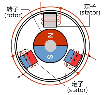
1. BLDC, commonly known as brushless DC motor, has no commutator. Its stator is a coil made of copper wire, and the rotor is a permanent magnet.
2. BLDC control, also known as square wave control method. Divided into sensing and non sensing, the most common ones with sensing are Hall and magnetic encoders; The most commonly used method for non induction is back electromotive force observation.
Square wave control
A square wave is when only two phases of a three-phase motor are energized each time, with one phase suspended in the air.
To prevent short circuits, the upper and lower power transistors cannot be opened simultaneously.
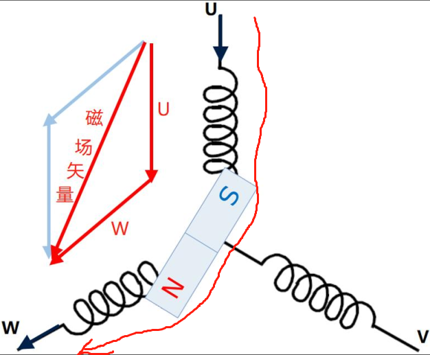
The direction of the magnetic field after the two phases are opened
According to the right-hand rule, the direction of the magnetic field generated by an energized conductor can be determined: when U-W is connected, the magnetic field generated by the two coils is combined to form the magnetic field vector. (There is a principle of same-sex repulsion and opposite attraction between magnets)
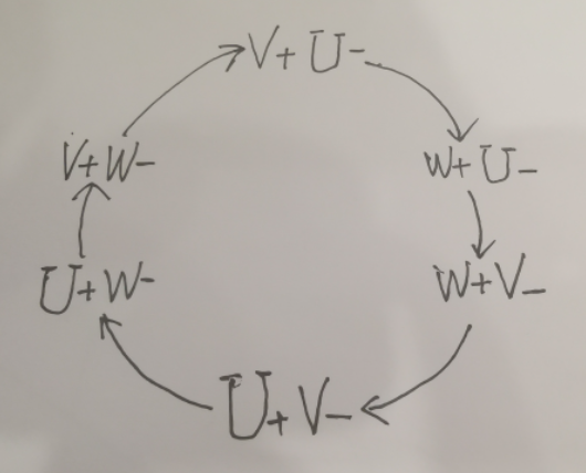
There are six types of three-phase combinations:
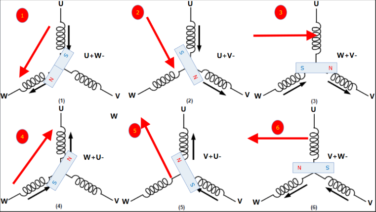
Clockwise we call it forward, counterclockwise we call it reverse
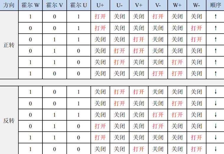
V+U-W+U-W+V - U+V - U+W - V+W - V+W - (There is a characteristic that changes in the order of UVW are forward rotation) W+W+U+U+V+V+, and the same goes for negative.
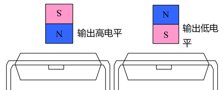
Hall serves as a position detector to determine which sector our rotor has turned to.
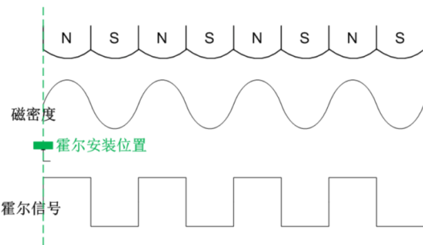
Hall principle: magnetic sensitive components
What is the order of 546231?
This is not a sector!!!!
Actually, in the end, we all need to control the motor through software.
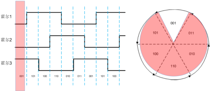
Three Halls make up a 3-bit wide binary number: 101, 001, 011
So we made the following assumptions: the U-value of the Hall sensor is the high bit 2, the V-value is bit 1, and the W-value is bit 0
We can calculate a Hall value accordingly:
And 546231 is the corresponding Hall value during normal transmission.
What should be noted when implementing Hall value software?
Hall is just three high and low level signals, the key is when to read this value.
Suggest placing it in the interrupt, don‘t ask why, it‘s about real-time performance, especially when the speed is too high. You don‘t have time to process the data, which leads to untimely commutation and inability to increase the speed!!!
HallDate=0;
HallDate=U<<2 | V<<1 | W<<0;
And operations that can be completed using shifts, do not use addition, subtraction, multiplication, and division. Bitwise operations are the fastest in C.
At this point, the HallDate you read is a number from 0 to 7, why are there still 0 and 7?
0 means the Hall value was not read, and 7 means the Hall value has been interfered with. Anyway, there is a problem, check it quickly!
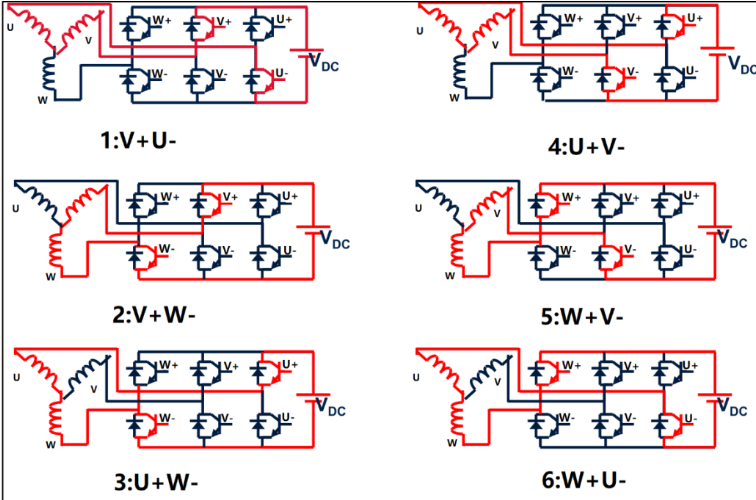
What is the half bridge of a three-phase inverter circuit
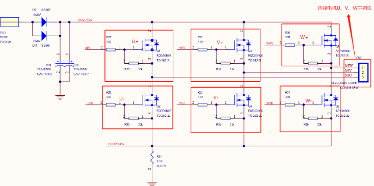
What we often refer to as upper bridge arm conduction or lower bridge arm conduction must refer to a certain half bridge.
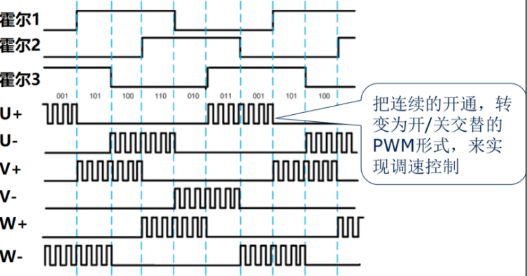
Why use PWM?
According to the above understanding, as long as the upper and lower bridge arms of the power transistor are open, how can PWM be introduced again?
Because when we directly load the power supply onto the coil and let it continue for a period of time, it will cause the motor to run at a very high speed. What about control?
So how do we replace the continuous high and low levels with PWM, using PWM to modulate, it is very convenient to control the current of the coil, and then control the rotor torque and speed (by adjusting the duty cycle).
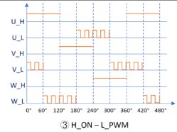
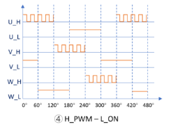
When we look at other people‘s code, we often see things like H-ON-L_PWM, H-PWM-L-ON
What is this?
In fact, it is the PWM adjustment method. It is not mentioned above that better control of the motor is necessary, and PWM is introduced, but there are also many ways of PWM adjustment.
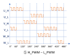
In theory, there should be 5 types, but let‘s only talk about the most common three
HYON-L-PWM: The upper half bridge of one phase always maintains a high level (i.e. the upper half bridge is normally open and conducting), while the lower half bridge of the other phase is always controlled in PWM mode
Disadvantages of BLDC square wave
One square wave control generates a large amount of heat and results in significant losses. Because heat generation is proportional to the square of the current, the phase current of a square wave drive motor only has two states: on and off, and the peak ripple current of the coil current is large.
The magnetic field generated by 2 is discontinuous and jumps, causing significant torque ripple. Causing vibration, generating noise, and reducing the performance of onboard chips or sensors.
Of course, there are also benefits, such as low hardware cost and simple control algorithms.
————————————————————————————————————————————————
Copyright Statement: This article is an original article by the blogger and follows the CC 4.0 BY-SA copyright agreement. Please include the original source link and this statement when reprinting.
Original link: https://blog.csdn.net/weixin_43824188/article/details/129547019
|
Disclaimer: This article is transferred from other platforms and does not represent the views and positions of this site. If there is any infringement or objection, please contact us to delete it. thank you! |


 Business consulting

 13823761625
 Mail me