


Some countermeasures to suppress electromagnetic interference of power module
Time:2024-04-06
Views:95
How to suppress electromagnetic interference has always been a problem that can not be ignored in the design of switching power module, which is not only related to the reliability of the power module itself, but also related to the safety and stability of the entire application system. Only by suppressing all kinds of noise interference of the switching power module can the switching power module be more widely used.
1.Definition of electromagnetic interference
Electro Magnetic Interference (EMI) refers to any electromagnetic phenomenon in the conduction or electromagnetic field accompanied by the action of voltage or current, which can reduce the performance of a device, equipment or system, or may have adverse effects on living organisms or substances.
2.Second, the generation of electromagnetic interference
(1 The generation of electromagnetic interference
Disturbance source, sensitive equipment and coupling path are called three elements of electromagnetic interference. For switching power modules, noise is generated by sharp changes in current or voltage, that is, di/dt or dv/dt is large, so devices with high power and high frequency operation are sources of EMI noise. Specifically, the main sources are:
(1) external coupled interference (mainly generated at the input and output ends);
(2) switching tube;
(3) transformer;
(4) diode;
(5) energy storage inductance;
(6) Circuit interference caused by unreasonable PCB board layout and routing.
3.Third, countermeasures to suppress electromagnetic interference
People are always trying to get rid of one of the three elements of electromagnetic interference: shielding the source of disturbance, isolating the sensitive equipment, or cutting off the coupling path. From the energy point of view, electromagnetic interference is a kind of energy, can not not let it produce, only with certain ways to reduce its interference to the system. The methods available can be divided into two broad categories: one is to let the energy escape; The other is to keep the energy out. It can be said that one way is to reduce the amplitude of its production, the other is to cut off its transmission path.
Figure 1 EMI filter circuit
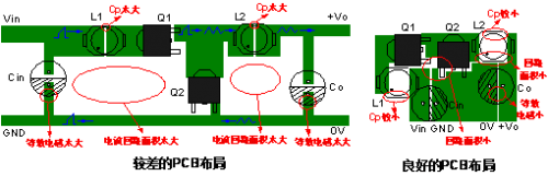
Figure 2 Comparison of two PCB layouts

Figure 3 Recommended EMC circuits of the DC-DC power module
1.Definition of electromagnetic interference
Electro Magnetic Interference (EMI) refers to any electromagnetic phenomenon in the conduction or electromagnetic field accompanied by the action of voltage or current, which can reduce the performance of a device, equipment or system, or may have adverse effects on living organisms or substances.
2.Second, the generation of electromagnetic interference
(1 The generation of electromagnetic interference
Disturbance source, sensitive equipment and coupling path are called three elements of electromagnetic interference. For switching power modules, noise is generated by sharp changes in current or voltage, that is, di/dt or dv/dt is large, so devices with high power and high frequency operation are sources of EMI noise. Specifically, the main sources are:
(1) external coupled interference (mainly generated at the input and output ends);
(2) switching tube;
(3) transformer;
(4) diode;
(5) energy storage inductance;
(6) Circuit interference caused by unreasonable PCB board layout and routing.
3.Third, countermeasures to suppress electromagnetic interference
People are always trying to get rid of one of the three elements of electromagnetic interference: shielding the source of disturbance, isolating the sensitive equipment, or cutting off the coupling path. From the energy point of view, electromagnetic interference is a kind of energy, can not not let it produce, only with certain ways to reduce its interference to the system. The methods available can be divided into two broad categories: one is to let the energy escape; The other is to keep the energy out. It can be said that one way is to reduce the amplitude of its production, the other is to cut off its transmission path.
The following is an analysis of specific aspects:
(1 Coupling of external interference (input and output)
(1.1) Input end
The input is the entrance of the entire power supply, and the noise inside the power supply can also be transmitted to the outside world, causing interference to the outside world. The usual strategy is to filter noise and interference by adding X capacitors, Y capacitors, differential mode inductors and common mode inductors to the input. Figure 1 is a more common EMI filter circuit.
Figure 1 EMI filter circuit
The filter circuit composed of L1, CY1 and CY2 can suppress the common mode interference signal on the power line. When there is a common mode interference current flowing through the coil, due to the homotropy of the common mode current, the magnetic field in the same direction will be generated in the coil and the inductive reactance of the coil will be increased, so that the coil behaves as a high impedance, resulting in a strong damping effect, so as to attenuate the common mode interference. Differential mode inductor L2 and X capacitor, composed of low-pass filter, can suppress differential mode interference on the power line.
(1.2) Output end
For the output, especially if there is a long output lead, after the power module is matched with the system, some noise interference inside the power supply may be coupled to the outside world by the output line, interfering with other electrical equipment. For this, the best way is to add some common mode filtering and differential mode filtering as well as dealing with input interference. In addition, the output line can also be fitted with a magnetic bead ring; Use twisted pair or shielded wire to achieve the purpose of suppressing EMI interference.
2. Switch tube
In the working process of the power module, due to the existence of the switching tube junction capacitance, the switching tube will produce burrs and spikes when it is quickly switched, so that some will be transmitted or emitted. In addition, the junction capacitance of the switch tube and the winding leakage of the transformer may also cause resonance and emit interference.
Possible countermeasures are:
(2.1) The D pole and G pole string of the switching tube are added with a magnetic bead ring, which is equal to adding a small inductance to reduce the current change rate of the switching tube, so as to achieve the purpose of reducing the peak.
(2.2) Add a buffer circuit or use soft switching technology at the switch tube to reduce the peak of the switch tube when it is working quickly, so that its voltage or current can rise slowly.
(2.3) If the pressure difference between the switch tube and the peripheral components is reduced, the degree to which the junction capacitance of the switch tube can be charged will be reduced to a certain extent.
(2.4) Increase the G pole driving resistance of the switching tube.
3. Transformer
Transformer is the energy storage component of power module, in the process of energy charging and discharging, it may produce noise interference. The leakage induction can form an oscillation circuit with the distributed capacitance in the circuit, which causes the circuit to generate high-frequency oscillation and radiate electromagnetic energy outwards, causing electromagnetic interference. The potential difference between the primary and secondary windings also produces a high-frequency change, through the coupling of parasitic capacitors, resulting in a common-mode conducted EMI current interference flowing between the primary and secondary sides.
Possible countermeasures are:
(1) transformer plus shielding.
Shielding can be divided into electrical shielding and magnetic shielding, the main role of electrical shielding is to isolate the primary interference signal from the secondary.A layer of copper foil (internal shielding) can be wrapped between the primary and secondary, but the head and tail can not be short-circuited, and the copper foil should be grounded, so that a capacitor is formed between the primary winding and the copper foil, and the common-mode conduction interference signal forms a loop through the capacitor - copper foil - grounding, which can not enter the secondary winding to play the role of electrical shielding.The magnetic shield is a copper foil connected end to end in the outer wire bag of the transformer (outer shield). Copper foil is a good conductor. When the high-frequency alternating leakage flux passes through the copper foil, eddy currents will be generated, and the direction of the magnetic field generated by the eddy current is just opposite to the direction of the leakage flux, and part of the leakage flux can be offset.
(2) The sandwich winding method can reduce the high-frequency interference of the primary coupling to the transformer core. Because the primary is far away from the magnetic core, the secondary voltage is low, so the high-frequency interference caused is small.
(3) Reduce the working frequency and slow down the rapid charging and discharging of energy.
(4) Reliable isolation of the primary side and the secondary side, and ground connection Y capacitance between the primary side and the secondary side.
(5) Minimize the leakage of the transformer, improve the distribution parameters of the circuit, and reduce the interference to a certain extent.
4. Diode
The diode will have a peak in the process of rapid cutoff and conduction, especially the rectifier diode, which in the reverse recovery process, the parasitic inductance and capacitance of the circuit will have high frequency oscillation, resulting in electromagnetic interference.
Possible countermeasures are:
(4.1) Add RC absorption circuit, so that the energy of the diode can be gently discharged.
(4.2) A magnetic bead ring is placed on the cathode tube foot so that its current cannot be mutated to reduce spikes.
5. Energy storage inductance
(5.1) Similar to a transformer, it can be shielded.
(5.2) Adjust its parameters to avoid oscillation with the capacitor of the loop.
6, PCB board layout and wiring
To be precise, PCB is the coupling channel of the above interference source, and the advantages and disadvantages of PCB directly correspond to the good or bad suppression of the above EMI source.
At the same time, the unreasonable layout and wiring of the devices on the PCB board will cause EMI interference.
Possible countermeasures are:
(1) The most effective way to reduce interference is to reduce the area of each current loop (magnetic field interference) and the area and length of the charged conductor (electric field interference).
(2) The different ground lines in the circuit, especially analog and digital ground, should be separated.
(3) The power line and ground line of the PCB are as wide as possible to reduce the line impedance, thereby reducing the interference noise caused by the public impedance.
(4) Impedance matching must be considered for the transmission signal line.
Figure 2 Comparison of two PCB layouts
For the smaller DC-DC power module, our usual practice is to achieve electromagnetic interference suppression by building peripheral circuits to ensure the reliability of the application system. The EMC recommended circuit is shown in Figure 2, where ① part is used for EMS testing and ② part is used for EMI filtering.
Figure 3 Recommended EMC circuits of the DC-DC power module
|
Disclaimer: This article is transferred from other platforms and does not represent the views and positions of this site. If there is any infringement or objection, please contact us to delete it. thank you! |


 Business consulting

 13823761625
 Mail me