


Working area and working principle of voltage comparator
Time:2024-04-08
Views:94
What is a voltage comparator
Voltage comparators are usually composed of integrated op-amps. Different from common op-amp circuits, integrated op-amps in comparators are mostly in open-loop or positive feedback state. As long as a small signal is added at the two input ends, the op amp will enter the nonlinear region, which belongs to the nonlinear application range of the integrated op amp. In the analysis of comparators, the principle of virtual break is still valid, and the concepts of virtual short and virtual ground are only applicable when judging the critical case.
Voltage comparators usually operate in the nonlinear region. This is because the main function of the voltage comparator is to compare the magnitude of two voltages and output a high or low level signal based on the comparison results. In this process, it does not need to linearly amplify the input signal, but directly outputs a digital signal representing the comparison result according to the relationship between the input signal and the reference voltage.
Therefore, the operating area of the voltage comparator mainly depends on the design and working principle of its internal circuit, rather than the need to work in a specific linear region like a linear amplifier. Of course, the specific voltage comparator may vary depending on the design, manufacturing process and application needs, but the basic working principle and working area are similar.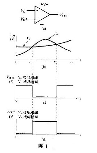
If VA is input to the inverting end and VB is input to the in-phase end, the voltage changes of VA and VB are still shown in Figure 1 (b), then the Vout output is shown in Figure 1 (d). Compared with Figure 1 (c), the output level is inverted. The change of output level is related to the input end of VA and VB.
Is a voltage comparator the same as a voltage follower
Voltage comparator and voltage follower are two kinds of circuit components with different functions, and their applications and functions in circuits are significantly different.
The main function of a voltage comparator is to compare the voltage of two input signals and output the difference between them. This kind of circuit is usually used in switch control, power supply monitoring and measurement. A common type of voltage comparator is a zero-crossing comparator, which compares an analog input signal with a fixed reference voltage. The operating characteristics of the comparator are usually described by threshold voltage and transmission characteristics.
The voltage follower, also known as the buffer amplifier, has the main feature that its output voltage is the same as the input voltage, there is no amplification effect of gain, but the current gain is increased. The main function of the voltage follower is to convert the impedance of the input voltage into a lower output voltage impedance, providing current amplification and voltage following functions. This circuit is generally used as an output stage or isolation stage in the actual circuit, which can connect two circuits to reduce the impact of direct connection between circuits and play a buffer role.
Therefore, the voltage comparator and the voltage follower are different in function, application, and operating principle, and cannot be considered the same or interchangeable circuit elements.
Voltage comparators are usually composed of integrated op-amps. Different from common op-amp circuits, integrated op-amps in comparators are mostly in open-loop or positive feedback state. As long as a small signal is added at the two input ends, the op amp will enter the nonlinear region, which belongs to the nonlinear application range of the integrated op amp. In the analysis of comparators, the principle of virtual break is still valid, and the concepts of virtual short and virtual ground are only applicable when judging the critical case.
Voltage comparators usually operate in the nonlinear region. This is because the main function of the voltage comparator is to compare the magnitude of two voltages and output a high or low level signal based on the comparison results. In this process, it does not need to linearly amplify the input signal, but directly outputs a digital signal representing the comparison result according to the relationship between the input signal and the reference voltage.
Therefore, the operating area of the voltage comparator mainly depends on the design and working principle of its internal circuit, rather than the need to work in a specific linear region like a linear amplifier. Of course, the specific voltage comparator may vary depending on the design, manufacturing process and application needs, but the basic working principle and working area are similar.
The operating range of the voltage comparator is usually within a certain voltage range, and the specific operating range depends on the design and specifications of the comparator. In general, voltage comparators may have an operating range from a few volts to tens of volts, and some comparators may have a wider operating range and can handle higher or lower voltages.
Simply put, the voltage comparator compares the size of two analog voltages (there are also two digital voltage comparisons, which are not introduced here) and determines which of them is high, as shown in Figure 1. Figure 1 (a) is the comparator, which has two inputs: in-phase input (" + ") and inverting input (" - "), and an output Vout (output level signal). In addition, there is a power supply V+ and ground (this is a single power comparator), the input voltage of the in-phase end is VA, and the input of the reverse phase end is VB. The changes of VA and VB are shown in Figure 1 (b). At time 0 ~ t1, VA "VB; At t1 ~ t2, VB is VA; At t2 ~ t3, VA is VB. In this case, the output of Vout is shown in Figure 1 (c) : When VA is VB, the Vout output is high (saturated output); "VB" when VA, Vout output low level. According to the output level, you can know which voltage is high.
Simply put, the voltage comparator compares the size of two analog voltages (there are also two digital voltage comparisons, which are not introduced here) and determines which of them is high, as shown in Figure 1. Figure 1 (a) is the comparator, which has two inputs: in-phase input (" + ") and inverting input (" - "), and an output Vout (output level signal). In addition, there is a power supply V+ and ground (this is a single power comparator), the input voltage of the in-phase end is VA, and the input of the reverse phase end is VB. The changes of VA and VB are shown in Figure 1 (b). At time 0 ~ t1, VA "VB; At t1 ~ t2, VB is VA; At t2 ~ t3, VA is VB. In this case, the output of Vout is shown in Figure 1 (c) : When VA is VB, the Vout output is high (saturated output); "VB" when VA, Vout output low level. According to the output level, you can know which voltage is high.
If VA is input to the inverting end and VB is input to the in-phase end, the voltage changes of VA and VB are still shown in Figure 1 (b), then the Vout output is shown in Figure 1 (d). Compared with Figure 1 (c), the output level is inverted. The change of output level is related to the input end of VA and VB.
Is a voltage comparator the same as a voltage follower
Voltage comparator and voltage follower are two kinds of circuit components with different functions, and their applications and functions in circuits are significantly different.
The main function of a voltage comparator is to compare the voltage of two input signals and output the difference between them. This kind of circuit is usually used in switch control, power supply monitoring and measurement. A common type of voltage comparator is a zero-crossing comparator, which compares an analog input signal with a fixed reference voltage. The operating characteristics of the comparator are usually described by threshold voltage and transmission characteristics.
The voltage follower, also known as the buffer amplifier, has the main feature that its output voltage is the same as the input voltage, there is no amplification effect of gain, but the current gain is increased. The main function of the voltage follower is to convert the impedance of the input voltage into a lower output voltage impedance, providing current amplification and voltage following functions. This circuit is generally used as an output stage or isolation stage in the actual circuit, which can connect two circuits to reduce the impact of direct connection between circuits and play a buffer role.
Therefore, the voltage comparator and the voltage follower are different in function, application, and operating principle, and cannot be considered the same or interchangeable circuit elements.
|
Disclaimer: This article is transferred from other platforms and does not represent the views and positions of this site. If there is any infringement or objection, please contact us to delete it. thank you! |


 Business consulting

 13823761625
 Mail me