


Dynamically adjust the appropriate output voltage
Time:2024-04-13
Views:70
The power supply is usually set to a fixed output voltage to power the electrical load. However, some applications require variable supply voltages. For example, in some cases, a microcontroller can operate more efficiently if the kernel voltage is adjusted to the corresponding operating state. This article will show how to adjust the output voltage of a power supply in real time using a dedicated digital-to-analog converter (DAC) developed for this purpose.

Figure 1. A switching regulator with potentiometers in the resistance path to adjust the output voltage
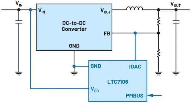
Figure 2. LTC7106 DAC for dynamic adjustment of switching regulator output voltage

Figure 3.LTpowerPlay graphical user interface that controls the LTC7106 via PMBus or I2C
The output voltage of a voltage converter is usually set by a resistor divider. This is very effective for fixed voltages. However, if you want to change the output voltage, you must adjust one of the resistance values of the divider. This can be done dynamically with a potentiometer. Figure 1 shows one such simple circuit, which uses a switching regulator IC with a step-down topology.
Figure 1. A switching regulator with potentiometers in the resistance path to adjust the output voltage
nfortunately, in many applications, a circuit with a potentiometer (as shown in Figure 1) is not very practical. Often a digital signal must be used to set the voltage. A good solution is to feed a smaller positive or negative current into the FB node. Small Dacs developed specifically to dynamically adjust the output voltage can be used for this purpose.
Figure 2 shows an example circuit containing an unspecified voltage converter that the LTC7106DAC plugs into the wiring of the feedback path. In principle, any voltage converter with an externally accessible feedback pin can operate in this way.
The LTC7106 has a current output whose current feeds into the resistance divider, so for different output voltages, the reference voltage of the switching regulator IC appears on the FB pin of the switching regulator. In this way, the output voltage is set when the FB pin receives the required regulation voltage.
Unlike many other Dacs with a current output, the LTC7106 is designed so that no current flows on the IDAC pin as long as a valid digital command is not present. Therefore, no unwanted voltage is set during circuit startup.
Figure 2. LTC7106 DAC for dynamic adjustment of switching regulator output voltage
The LTC7106 is a 7-bit DAC that can operate at 1 µA per LSB or 4 µA per LSB, depending on the application. The highest resolution is achieved by 1 µA per LSB. It is recommended that the resistance divider of the switching regulator be set to 1 µA per LTC7106 LSB..
The output of the current DAC has an accuracy of ±0.8% in the positive range and ±1.5% in the negative range, each accuracy measured over the full temperature range allowed.
The output of the current DAC has an accuracy of ±0.8% in the positive range and ±1.5% in the negative range, each accuracy measured over the full temperature range allowed.
Figure 3.LTpowerPlay graphical user interface that controls the LTC7106 via PMBus or I2C
Figure 3 shows the graphical user interface LTpowerPlay, which you can use to easily program the LTC7106.
Of course, even in circuits with the LTC7106, there are limits to the adjustable range of the output voltage. A switching regulator or linear regulator can only produce the expected voltage. Linear or step-down switching regulators can only produce an output voltage lower than the input voltage. In addition, it is recommended to check the voltage conversion circuit to ensure that the control loop is stable and that the output voltage ripple is within a reasonable range of the desired output voltage.
Dynamic adjustment of the output voltage can be easily achieved with small current-type Dacs such as the LTC7106. This feature is designed for reliable operation with as few wires as possible.
|
Disclaimer: This article is transferred from other platforms and does not represent the views and positions of this site. If there is any infringement or objection, please contact us to delete it. thank you! |


 Business consulting

 13823761625
 Mail me