


Is the interference waveform from probe grounding or channel crosstalk?
Time:2024-04-17
Views:37
When measuring the output signal of switching power supply with oscilloscope, many engineers will find that there is mutual interference between the two measurement channels. Does this interference come from between channels? Let‘s test it out.
1. Background overview
When the oscilloscope is used to measure the output signal of the switching power supply, it is found that there is mutual interference (crosstalk) between the two measurement channels. So will the two measurement channels interfere with each other?
Test method: Channel 1 measures small signal (100mv/div), channel 2 measures large signal (5V/div), and observe the interaction of signals.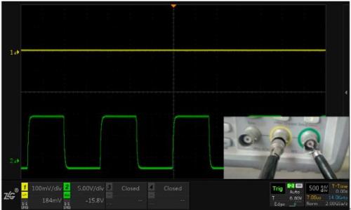
Figure 1 CH1, CH2 measurement signal generator output, well grounded
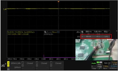
Figure 2 CH1 Using clamps to measure power output, CH2 suspended
Note: Although the amplitude of the channel 1 signal is very small, the interference at 600K frequency can be located through FFT analysis.
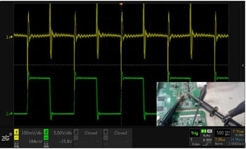
Figure 3 CH1 uses clamps to measure power output, CH2 uses clamps to measure inductance, single point ground
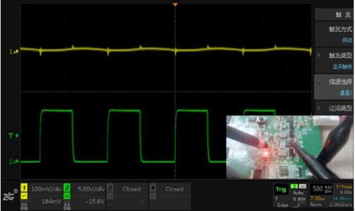
Figure 5 The CH1 uses a ground spring to measure the power output, and the CH2 uses a clamp to measure the inductance, each grounded
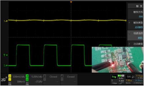
Figure 6 CH1 uses a ground spring to measure the power output and CH2 uses a ground spring to measure the inductance, each grounded
1. Background overview
When the oscilloscope is used to measure the output signal of the switching power supply, it is found that there is mutual interference (crosstalk) between the two measurement channels. So will the two measurement channels interfere with each other?
Test method: Channel 1 measures small signal (100mv/div), channel 2 measures large signal (5V/div), and observe the interaction of signals.
First, the standard signal source is used to verify the factors affecting the channel isolation;
Different measurement methods are then used to verify the influence factors of crosstalk.
2. Channel isolation test and verification
As shown in Figure 1, the input signals of the two channels of the oscilloscope are directly output from the signal generator, and it can be found that the signal of channel 2 has no effect on channel 1, and the channel isolation is good. Of course, the index of channel isolation has a more rigorous test method, here is a simple test.
Figure 1 CH1, CH2 measurement signal generator output, well grounded
Third, the real cause of interference - ground!
The above interference is mainly related to the use of the probe, especially the connection of the probe ground wire. The measurement process is as follows, while recording the crosstalk of the test mode:
1. The probe of channel 1 is grounded with crocodile clamp, and channel 2 is closed (to prove the original signal of channel 1, see Figure 2).
Figure 2 CH1 Using clamps to measure power output, CH2 suspended
Note: Although the amplitude of the channel 1 signal is very small, the interference at 600K frequency can be located through FFT analysis.
2. Channels 1 and 2 probes are only connected to one another using crocodile clips (crosstalk is very serious, see Figure 3);
Figure 3 CH1 uses clamps to measure power output, CH2 uses clamps to measure inductance, single point ground
3. Channel 1 and 2 probes are grounded with alligator clips respectively (serious crosstalk, see Figure 4);
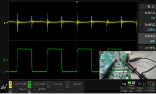
Figure 4 CH1 uses clamps to measure power output, CH2 uses clamps to measure inductance, each grounded
4. Use spring ground in channel 1 and alligator clamp ground in channel 2 (little crosstalk, FIG. 5);
Figure 5 The CH1 uses a ground spring to measure the power output, and the CH2 uses a clamp to measure the inductance, each grounded
5. Channel 1 and 2 probes are grounded separately using springs (minimum crosstalk, see Figure 6);
Figure 6 CH1 uses a ground spring to measure the power output and CH2 uses a ground spring to measure the inductance, each grounded
Iv. Summary
When the measuring probe and ground wire are well connected, the interference between the channels of the oscilloscope is small;
Interference from the influence of parasitic parameters at the ground of the test probe, such as lead inductance;
When measuring two signals at the same time, in order to avoid mutual interference of the grounding loop, it should be grounded separately;
l Use ground springs when measuring sensitive signals and interface terminals if necessary.
|
Disclaimer: This article is transferred from other platforms and does not represent the views and positions of this site. If there is any infringement or objection, please contact us to delete it. thank you! |


 Business consulting

 13823761625
 Mail me