


BLDC motor control algorithm
Time:2024-04-21
Views:31
Brushless motors are self-commutating (self-direction conversion), so it is more complicated to control.
BLDC motor control requires an understanding of the rotor position and mechanism of the motor for rectification steering. For closed-loop speed control, there are two additional requirements, namely measurement of rotor speed or motor current and PWM signal to control motor speed as well as power.
BLDC motors can use either side-lined or centre-lined PWM signals according to application requirements. Most applications require only a speed change operation and will use six independent edge arrays of PWM signals. This provides the highest resolution. If the application requires server positioning, power braking, or power reversal, a complementary center-aligned PWM signal is recommended.
To sense rotor position, BLDC motors use Hall effect sensors to provide absolute positioning sensing. This leads to more line use and higher costs. Sensorless BLDC control eliminates the need for Hall sensors and instead uses the back electromotive force (EMF) of the motor to predict the rotor position. Sensorless control is essential for low-cost variable speed applications like fans and pumps. With BLDC motors, refrigerator and air conditioning compressors also require sensorless control.
Insertion and replenishment of idle time:
Most BLDC motors do not require complementary PWM, no-load time insertion, or no-load time compensation. The only BLDC applications that may require these characteristics are high-performance BLDC servomotors, sine-wave excited BLDC motors, brushless AC, or PC synchronous motors.
Control algorithms Many different control algorithms are used to provide control of BLDC motors. Typically, the power transistor is used as a linear regulator to control the motor voltage. This method is not practical when driving high power motors. High power motors must be PWM controlled and require a microcontroller to provide starting and control functions.
The control algorithm must provide the following three functions:
▪ PWM voltage for motor speed control;
▪ A mechanism for commutating into the motor;
A method for predicting rotor position using a back electromotive force or Hall sensor;
Pulse width modulation is only used to apply a variable voltage to the motor winding. The effective voltage is proportional to the PWM duty cycle. When properly commutated, BLDC has the same torque-speed characteristics as the following DC motors. Variable voltage can be used to control the speed and torque of the motor.
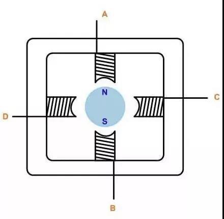
Figure 1
The commutation of the power transistor enables the appropriate winding in the stator to generate the best torque according to the rotor position. In a BLDC motor, the MCU must know the position of the rotor and be able to make the commutation at the right time.
The trapezoidal commutation of BLDC motors is one of the easiest ways to use the so-called trapezoidal commutation for DC brushless motors.
The trapezoidal commutation of BLDC motors is one of the easiest ways to use the so-called trapezoidal commutation for DC brushless motors.
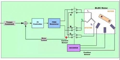
Figure 2: Simplified block diagram of a ladder controller for BLDC motors
In Figure 2, the current is controlled each time through a pair of motor terminals, and the third motor terminal is always electrically disconnected from the power supply.
Three Hall devices embedded in the large motor are used to provide digital signals that measure the rotor position in a 60-degree sector and provide this information on the motor controller. Since the current on two windings is equal at a time and the current on the third winding is zero, this method can only produce a current space vector with one of the six directions. As the motor rotates, the current at the end of the motor realizes an electrical switch (commutation) at 60 degrees per revolution, so the current space vector is always at the position closest to 30 degrees of the 90 degree phase shift.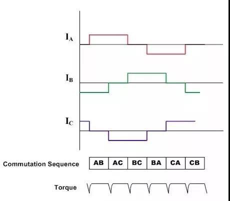
Three Hall devices embedded in the large motor are used to provide digital signals that measure the rotor position in a 60-degree sector and provide this information on the motor controller. Since the current on two windings is equal at a time and the current on the third winding is zero, this method can only produce a current space vector with one of the six directions. As the motor rotates, the current at the end of the motor realizes an electrical switch (commutation) at 60 degrees per revolution, so the current space vector is always at the position closest to 30 degrees of the 90 degree phase shift.
Figure 3: Ladder control: Torque at the drive waveform and rectification
Therefore, the current wave pattern of each winding is trapezoidal, starting from zero to positive current to zero and then to negative current.
In motor applications such as air conditioners and refrigerators, Hall sensors are not a constant choice. A back electromotive force sensor induced in a non-connected winding can be used to achieve the same result.
These trapezoidal drive systems are very common because of the simplicity of their control circuits, but they suffer from torque ripple problems during rectification.
The sinusoidal commutation trapezoidal commutation of BLDC motors is not enough to provide balanced, accurate brushless DC motor control. This is mainly because the torque generated in a three-phase brushless motor (with an orthodox wave back electromotive force) is defined by the following equation:
Shaft torque =Kt [IRSin (o) +ISSin (o+120) +ITSin (o+240)] where:
o is the electrical Angle of the rotating shaft
Kt is the torque constant of the motor
IR, IS and IT are phase currents
If the phase current is sinusoidal: IR=I0Sino; IS=I0Sin (+120o); IT=I0Sin (+240o)
You will get: shaft torque =1.5I0*Kt (a constant independent of shaft Angle)
The sinusoidal commutator brushless motor controller strives to drive three motor windings, whose three currents change sinusoidal smoothly as the motor rotates. The relative phases of these currents are selected so that they will produce a smooth rotor current space vector in a direction orthogonal to the rotor and with invariants. This eliminates the torque ripple and steering pulse associated with steering.
In order to generate a smooth sine wave modulation of the motor current as the motor rotates, an accurate measurement of the rotor position is required. The Hall device only provides a rough calculation of the rotor position, which is not enough to meet the purpose requirements. For this reason, angular feedback from an encoder or similar device is required.
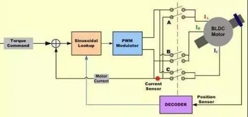
Figure 4: Simplified block diagram of BLDC motor sine wave controller
Since the winding currents must be combined to produce a steady constant rotor current space vector, and each positioning of the stator windings is at an Angle of 120 degrees, the currents of each line set must be sinusoidal and phase-shifted at 120 degrees. The position information in the encoder is used to synthesize two sine waves, and the phase shift between the two is 120 degrees. These signals are then multiplied by the torque value, so that the amplitude of the sine wave is proportional to the desired torque. As a result, the two sine wave current commands are properly phased to generate a rotating stator current space vector in the orthogonal direction.
Since the winding currents must be combined to produce a smooth constant rotor current space vector, and each positioning of the stator windings is at an Angle of 120 degrees apart, each line set of sinusoidal current command signals outputs a pair of P-I controllers that modulate the current in the two appropriate motor windings. The current in the third rotor winding is the negative sum of the controlled winding current and therefore cannot be controlled separately. The output of each P-I controller is sent to a PWM modulator and then to the output bridge and two motor terminals. The voltage applied to the third motor terminal is derived from the negative sum of the signals applied to the first two lines for three sinusoidal voltages separated by 120 degrees.
Since the winding currents must be combined to produce a smooth constant rotor current space vector, and each location of the stator windings is 120 degrees apart, the actual output current waveform precisely tracks the sinusoidal current command signal as a result of each line set, and the resulting current space vector rotates smoothly, is quantitatively stable and positioned in the desired direction.
Since the winding currents must be combined to produce a stable constant rotor current space vector, and each location of the stator windings is 120 degrees apart, each line group is generally turned by trapezoidal rectification, and the stable control of sinusoidal rectification steering results cannot be achieved. However, because it is highly efficient at low motor speeds, it will separate at high motor speeds. This is due to the increase in speed, and the current reflux controller must track a sinusoidal signal that increases in frequency. At the same time, they must overcome the back electromotive force of the motor, which increases at amplitude and frequency as the speed increases.
Since the winding currents must be combined to produce a smooth constant rotor current space vector, and each positioning of the stator windings is 120 degrees apart, so each line set due to the P-I controller has limited gain and frequency response, interference with the time variable of the current control loop will cause phase lag and gain error in the motor current, the higher the speed, the greater the error. This interferes with the direction of the current space vector relative to the rotor, causing displacement with the orthogonal direction.
Since the winding current must be combined to produce a smooth constant rotor current space vector, and each positioning of the stator winding is 120 degrees apart, so each line group can produce a small torque through a certain amount of current when this is generated, so more current is needed to maintain the torque, and the efficiency is reduced.
Since the winding current must be combined to produce a smooth constant rotor current space vector, and each positioning of the stator winding is 120 degrees apart, so each line group can produce a small torque through a certain amount of current when this is generated, so more current is needed to maintain the torque, and the efficiency is reduced.
Since the winding currents must be combined to produce a smooth constant rotor current space vector, and each positioning of the stator windings is at an Angle of 120 degrees apart, this reduction will continue with each line set as the speed increases. At some point, the current‘s phase shifts by more than 90 degrees. When this happens, the torque is reduced to zero. Through the combination of sinusoids, the velocities at this point result in a negative torque and therefore cannot be achieved.
01 AC motor control algorithm
1. Scalar control
Scalar control (or V/Hz control) is a simple way to control the speed of an ordered motor. The steady-state model of the command motor is mainly used to acquire technology, so transient performance is impossible to achieve. The system does not have a current loop. To control the motor, the three-phase power supply varies only in amplitude and frequency.
2, vector control or magnetic field oriented control
The torque in the motor varies with the function of the stator and rotor magnetic fields, and peaks when the two magnetic fields are orthogonal to each other. In scalar-based control, the Angle between the two magnetic fields varies significantly.
Vector control seeks to re-create orthogonal relationships in AC motors. In order to control the torque, each generates current from the generated magnetic flux to achieve the responsiveness of the DC machine.
Vector control of an AC command motor is similar to control of a separate excitation DC motor. In A DC motor, the field energy ΦF generated by the exciting current IF is orthogonal to the armature flux ΦA generated by the armature current IA. These magnetic fields are decoupled and stable with each other. Thus, when the armature current is controlled to control the torque, the field energy remains unaffected and a faster transient response is achieved.
Field-oriented control (FOC) for three-phase AC motors includes operations that mimic those of DC motors. All controlled variables are mathematically converted to DC instead of AC. The goal is to control torque and flux independently.
There are two methods of field oriented control (FOC) :
Direct FOC: The Rotor flux angle is calculated directly by the flux observer.
Indirect FOC: The Rotor flux angle is obtained indirectly by estimating or measuring the rotor speed and slip.
Vector control requires knowledge of the position of the rotor flux and can be calculated by advanced algorithms using knowledge of the terminal current and voltage (using the dynamic model of AC induction motors). However, from an implementation point of view, the need for computing resources is critical.
Vector control algorithms can be implemented in different ways. Feedforward techniques, model estimation, and adaptive control techniques can all be used to enhance response and stability.
3, AC motor vector control: in-depth understanding
At the heart of vector control algorithms are two important transformations: Clark transform, Park transform and their inversions. Using the Clark and Park transformations, the rotor current to the rotor area can be controlled. This allows a rotor control system to determine the voltage that should be supplied to the rotor to maximize torque under dynamically varying loads.
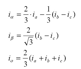
Clark transformation: Clark mathematical transformation modifies a three-phase system into two coordinate systems:
Where Ia and Ib are components of the orthogonal datum plane, Io is an unimportant homoplanar part.
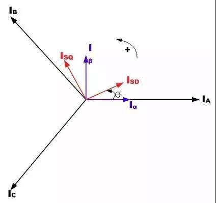
Figure 5: Relationship between three-phase rotor current and rotating reference frame
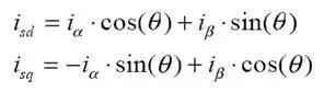
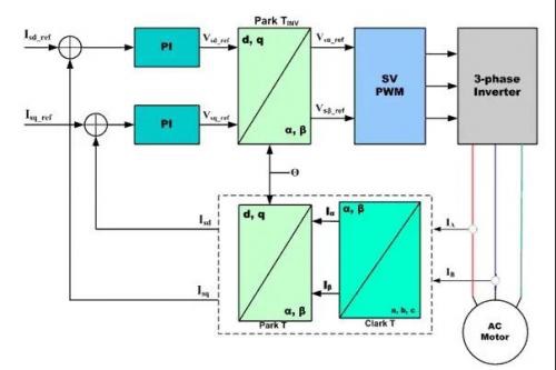
Figure 5: Relationship between three-phase rotor current and rotating reference frame
4. Park transformation: Park mathematical transformation converts the bidirectional static system into a rotating system vector
The two-phase α, β frame representation is calculated by Clarke transformation and then input into the vector rotation module, where it rotates at the Angle θ to conform to the d, q frames attached to the rotor energy. According to the above formula, the transformation of Angle θ is realized.
Clarke transform is the basic structure of magnetic field oriented vector control of AC motor using three-phase currents IA, IB and IC, in which the currents of IA and IB in the fixed coordinate stator phase are converted into Isd and Isq, which become the elements of Park transform d, q. The current Isd, Isq and instantaneous flow Angle θ calculated by the motor flux model are used to calculate the electric torque of the AC induction motor.
Figure 6: Basic principle of vector controlled AC motor
These derived values are compared with reference values and updated by the PI controller.
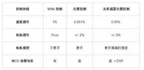
ble 1: Comparison of motor scalar control and vector control
02 BLDC vector control
An inherent advantage of vector-based motor control is that it is possible to use the same principle and select the appropriate mathematical model to separately control various types of AC, PM-AC or BLDC motors.
Vector control for BLDC motors BLDC motors are the primary choice for field-oriented vector control. Brushless motors with FOC can achieve higher efficiency, up to 95%, and are also very efficient for motors at high speeds.
1. Stepper motor control
Stepper motor control usually adopts bidirectional drive current, and its motor stepping is realized by switching winding in sequence. Usually this kind of stepper motor has 3 drive sequences:
① single-phase full step drive:
In this mode, the windings are charged in the following order, AB/CD/BA/DC (BA indicates that the charging of the winding AB is carried out in the opposite direction). This sequence is called the single-phase full-step mode, or wave-driven mode. At any one time, there is only one additional charge.
② Dual phase full step drive:
In this mode, the two phases are charged together, so that the rotor is always between the two poles. This mode is called biphase full step, this mode is the normal drive sequence of the bipolar motor, can output the maximum torque.
③ Half step mode:
This mode combines single-phase stepping and biphase stepping together: single-phase power, then double plus power, then single-phase power... Therefore, the motor runs in half-step increments. This mode is called half-step mode, and the effective step Angle of the motor per excitation is reduced by half, and the output torque is also lower.
The above three modes can be used to rotate in the opposite direction (counterclockwise), but not if the order is reversed.
Usually, the stepper motor has multiple poles in order to reduce the step Angle, but the number of windings and the drive sequence are constant.
2, general DC motor control algorithm
Speed control of general purpose motors, especially motors with 2 circuits:
▪ Phase Angle control
▪ PWM chopper control
① Phase Angle control
Phase Angle control is the simplest method to control the speed of general motors. The speed is controlled by changing the point arc Angle of the TRIAC. Phase Angle control is a very economical solution, however, it is not very efficient and prone to electromagnetic interference (EMI).
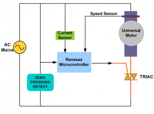
Figure 8: Phase Angle control for general-purpose motors
Figure 8 shows the mechanism of phase Angle control and is a typical application of TRIAC speed control. The phase movement of the TRIAC gate pulse produces an efficient voltage, thus producing different motor speeds, and a zero-cross detection circuit is used to establish a timing reference to delay the gate pulse.
②PWM chopper control
PWM control is a more advanced solution for general motor speed control. In this solution, the power MOSFETs, or IGBTs, turn on the high-frequency rectified AC line voltage to generate a time-varying voltage for the motor.
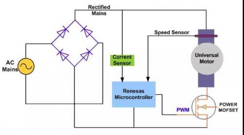
Figure 9: PWM chopper control for general-purpose motors
The switching frequency range is generally 10-20KHz to eliminate noise. This general purpose motor control method allows for better current control and better EMI performance, and therefore higher efficiency.Figure 9: PWM chopper control for general-purpose motors
The switching frequency range is generally 10-20KHz to eliminate noise. This general purpose motor control method allows for better current control and better EMI performance, and therefore higher efficiency.


 Business consulting

 13823761625
 Mail me