


Design method for improving transient response of power supply load
Time:2022-12-12
Views:1364
Electronic circuits generally need a voltage source that can maintain the output voltage within a specific tolerance range even when the load current transients to ensure the normal operation of the circuit. Design engineers must understand the principle of transient response, and use the correct design ideas to improve the transient response performance of power supply at a lower cost.
Transient is defined as "something that only lasts for a short time" However, with the increase of microprocessor‘s working speed and current demand, when the load current changes instantaneously, the ability of the regulator to maintain the output voltage within the specified range becomes a widespread problem. The power specification of a typical CPU chip requires that the power supply voltage should remain stable even if the load current changes 20 or 30A within a few hundred nanoseconds. It is not easy to achieve this performance index.
Transient response is probably one of the most difficult concepts to understand in electronic voltage regulation. In the past, someone once made a completely wrong statement: "Our new voltage regulator is so fast that you don‘t even need capacitors." On the contrary, when the load transients (no matter how fast the regulator is), you always need a capacitor.
In a word, in order to understand where to invest costs to improve system performance and how to save costs without sacrificing transients, you need to understand what transient response is and how it works.
Voltage regulation
Almost all electronic circuits need a stable voltage source, which is maintained within a specific tolerance range to ensure correct operation (typical CPU circuits only allow the maximum deviation between the voltage source and the rated voltage not to exceed ± 3%). This fixed voltage is provided by some types of voltage regulators. The output voltage is automatically detected by the resistance divider, and the error amplifier continuously adjusts the current source to maintain the output voltage stable at the rated voltage.
The voltage regulator must be able to keep the output voltage constant when the load current demand rises from zero to full load (about 20A or more). It is easy to do this when the load current demand changes slowly. However, if the load current "step" is fast enough, the regulator will not be able to provide a completely stable output voltage.
Key points for understanding load transient:
1. The voltage regulator acts as the voltage controlled current source driving the load (regulating the current source through the voltage feedback at the output end). The current source of the regulator can never change in zero time, so it can be concluded that if we make the load current change faster than the response speed of the regulator, the output voltage will change.
2. During the time interval when the control loop of the voltage regulator adjusts the load change, the only source for supplying the load current change (between the previous steady-state value and the new load current) is the output capacitance. Therefore, whether you like it or not, we must add output capacitors to try to maintain a constant output voltage during load transients. The system specification specifies the size and type of capacitors that must be used.
3. The faster the voltage regulator is, the better. The faster the control loop of the voltage regulator responds, the smaller the voltage change on the output capacitor before the loop corrects the transient. Therefore, it can be seen that a faster voltage regulator means that smaller output capacitors can be used (cost saving) with the same "load regulation tolerance range".
Load transient
In order to understand how the load transient occurs, the following is an example for analysis. In this example, a load transient occurs when the load current demand changes from IL1 to a greater value (IL2) in almost zero time. Before the transient, the voltage regulator is in steady state operation. At this time, IREG=IL1, and the output capacitor does not output current to the external circuit.
The current source (IREG) of the voltage regulator cannot change immediately, so at the moment of "t=0+" (that is, the moment when the load current increases to IL2), IREG=IL1. Through simple node analysis, it is concluded that the current source requires output capacitance at this time:
ICOUT=IL2-IL1
COUT will continue to supply current until the control loop increases IREG to IL2. During the period when the current must be supplied by the COUT, the voltage on both sides will decrease as the capacitor discharges. The internal parasitic equivalent series resistance (ESR) and equivalent series inductance (ESL) of the capacitor will also reduce the voltage on both sides of the COUT, as shown in Figure 1.
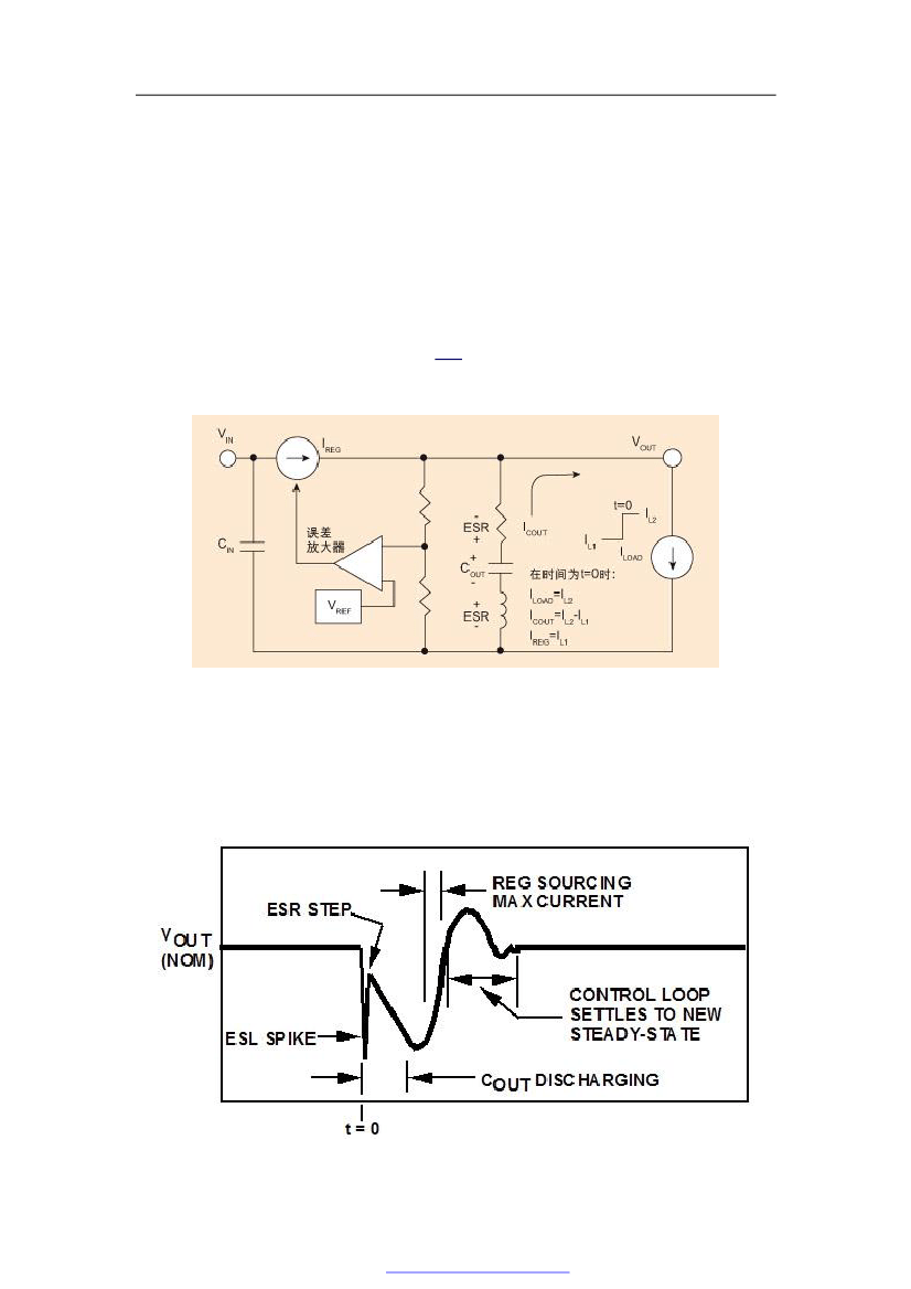

1: Occurrence of load transient due to current increase
Output voltage transient response
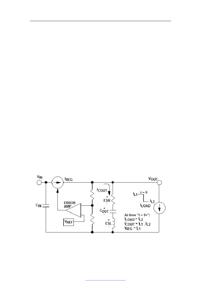
All capacitors contain ESR and ESL, which will have a significant impact on the transient response. The output voltage seen during an increased current load transient is similar to that shown in Figure 2.
Figure 2: VOUT after load step rise
The ESL causes the voltage on both sides of the capacitor to drop, which is strongly dependent on the rise time of the load transient: the faster the load changes, the greater the "spike" generated by the ESL on the output voltage waveform. The spike is very narrow in time, because the inductor only generates a voltage in response to the changing current, which can be obtained by the following formula:
V=Ldi/dt
When the load current reaches a new value (IL2), the voltage spike of ESL will end. The shorter the rise time of load current transient, the greater the influence of inductance. The ESR and ESL of large capacity ceramic capacitors are very low. They are usually used at the pins of devices, and these devices have corresponding requirements for rapidly rising load transients.
Whether the capacitor provides current or absorbs current (represented by "ESR step" on the waveform), the ESR of the output capacitor will cause the voltage to decrease. In particular, the "ESR step" here refers to the DC voltage change regulating the output terminal during load transient. This means that ESR becomes a key consideration when designing for the maximum allowable "voltage tolerance range" that must be met by regulating the voltage.
During the time interval before the current source of the voltage regulator is adjusted to a new value by the control loop, the voltage divider on both sides of the ESR reduces the output voltage (during this period, the amount of discharge charge of the COUT will also decrease accordingly).
Since these factors cause the regulated output voltage to drop below the rated value, the feedback from the output voltage to the error amplifier makes the current source IREG fully open, thus forcing the output voltage to return to the rated voltage. The output voltage will rise and overshoot exceeds the rated value. At this time, as the loop continues to adjust, the output voltage will be adjusted and decreased. In this case, the behavior of the loop accurately reflects the phase margin (loop stability). A well compensated loop with a phase margin greater than 40 ° will generate a transient that disappears rapidly and only contains a large offset (as shown in Figure 2). A relatively small phase margin will generate additional "ring cycles" in the loop setup behavior. The waveform in Figure 2 shows a "best case" description of stability, but it is not typical.
When the control loop reaches a new steady state (at this time, the current supplied by the current source of the voltage regulator is IL2), the output capacitor stops supplying current to the circuit again.
Why are load transients increasing/decreasing asymmetrical?
There are two types of load transients: a sudden increase or decrease in load current. The previous example shows how the output voltage changes when the load current suddenly increases. The following example will discuss what happens when the load current suddenly decreases (Figure 3).
Figure 3: Occurrence of current reduction load transient
In this example, the load current suddenly decreases from IL1 to IL2. Because IREG cannot immediately decrease to IL2, it will initially continue to provide current of IL1 size. Since the load now absorbs less current, the output capacitor must absorb the difference between IL1 and IL2, which will force the voltage on both sides of the COUT to rise.
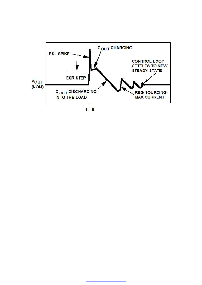
If the load current drops rapidly, it will generate a voltage spike on both sides of the ESL, and the current flowing through the ESR into the COUT will also cause an ESR "step" (Figure 4). After the peak, as the capacitor is charged from the absorption current (IL1 - IL2), the voltage on both sides of the COUT will increase.
Figure 4: VOUT when the load drops suddenly
Since the VOUT rises above the rated value, the feedback will eventually cause the control loop to close (or reduce) the current source IREG However, since most voltage regulators cannot absorb current to their output terminals, VOUT can only be reduced to the rated value again according to the discharge rate of COUT to the load (after IREG is reduced or closed). However, once the VOUT goes down to the rated value, the control loop will try again to open IREG and make the output rapidly swing up, causing this cycle to repeat until a new stable state condition is reached. At this time, because IREG is equal to IL2, there will be no current flowing into the COUT again.
The setting up time of the load decrease transient is usually greater than that of the load increase transient, because the former takes more time to discharge the excess voltage to the load in the COUT phase: since the load current demand is reduced, the discharge speed of the capacitor becomes slower. The load increase transient spends most of its time making the COUT swing up, and the regulator provides the maximum current (usually greater than the rated output current) in this mode. Compared with the reduction when discharging to the load, when driven in the positive direction by the above large current, the voltage on both sides of the COUT (that is, the regulated output voltage) will change faster.
The setting up time of the load decrease transient is usually greater than that of the load increase transient, because the former takes more time to discharge the excess voltage to the load in the COUT phase: since the load current demand is reduced, the discharge speed of the capacitor becomes slower. The load increase transient spends most of its time making the COUT swing up, and the regulator provides the maximum current (usually greater than the rated output current) in this mode. Compared with the reduction when discharging to the load, when driven in the positive direction by the above large current, the voltage on both sides of the COUT (that is, the regulated output voltage) will change faster.
This shows that in most cases, for the transient of load from 20% to 80% of rated current, the speed of output voltage re establishing to rated value is greater than the load transient of 80% to 20% of rated load current. Even if the total load current changes the same, the setup time (and the shape of the waveform) will also show great differences.
Optimize transient response
To obtain the optimal transient response, it is necessary to optimize the system design parameters. The following design suggestions are given.
1. Good steel is used on the blade. Large capacity ceramic capacitor is the best capacitor used to reduce transient in the world. Most motherboards are designed with a large number of ceramic capacitors (up to 22 μ F) These capacitors are directly installed on the pins of the device and can suppress transient after power on. The ESR resistance of large capacity ceramic capacitors is usually as low as milliohm, and the ESL value is also very low. No other type of capacitor can provide this level of performance for both ESR and ESL (although electrolytic capacitors can provide extremely low ESR).
2. A charge bank needs to be provided nearby. There is a practical limit to the capacitance that ceramic capacitors can provide, so they are usually "backed up" with electrolytic capacitors close to them, which can support the load when the initial load transient changes pass. In the past, tantalum capacitors were often used in this regard, but now they have been avoided due to the consideration of fire hazards. Sanyo‘s OSCON and POSCAP and Panasonic‘s SP electrolytic capacitors are high-capacity capacitors with extremely low ESR.
3. Cheap large capacitance. Generally, aluminum electrolyte capacitors with large capacity, low cost and high ESR are used at the input of voltage regulators. The reason is that the input terminal can tolerate capacitance with high ESR. This is because the "voltage step" caused by ESR does not directly affect the adjusted output voltage. On the contrary, it is suppressed by the "linear adjustment" function of the regulator, which usually provides up to 60~80dB attenuation of DC change at the input terminal of the regulator.
4. Voltage regulator bandwidth. The voltage regulator with large loop bandwidth can adjust the variable load more quickly, and reduce the number of high-capacity capacitors at the output side. This is achieved by the voltage regulator absorbing the charge stored in the high-capacity input capacitor shortly after the transient occurs. In general, the speed of linear regulators is often significantly faster than the speed of switches, because the unit gain bandwidth of linear regulators can be greater than 500 kHz (although due to power consumption constraints, many new processor chips require switching converters for high load current requirements). It is always correct to conclude that the faster the speed is, the higher the cost is, and without exception, the bandwidth of high current regulators needs to be increased.
|
Disclaimer: This article is transferred from other platforms and does not represent the views and positions of this site. If there is any infringement or objection, please contact us to delete it. thank you! |


 Business consulting

 13823761625
 Mail me