


Thermal integrity of IC packaging and PCB design
Time:2023-01-21
Views:1282
If you are now building a professionally designed circuit experimental board, you have completed all the simulation work required before layout, and checked the manufacturer‘s suggestions on how to obtain a good thermal design for a specific package. You have even carefully confirmed the preliminary thermal analysis equation written on paper and made sure that it does not exceed the IC node temperature and has a relatively loose tolerance. But later, when you turn on the power, you find that the IC feels very hot. You are very dissatisfied with this. Of course, cooling experts and reliability designers are more anxious. Now, what should you do?
When it comes to the reliability of the overall design, it is an important design consideration to keep the integrity of your circuit design under the condition of increasing ambient temperature by keeping the IC node temperature away from the absolute maximum level. This is especially true when you gradually approach the maximum power consumption level (Pd maximum) of the specific circuit design central chip.
The first step of thermal integrity analysis is to deeply understand the basic knowledge of IC package thermal index.
So far, the most common measure of package thermal performance is Theta JA, that is, the measured (or modeled) thermal resistance from the node to the environment (see Figure 1). Theta JA value is also the most important content to be explained (see Figure 2). Factors that can greatly affect the measurement and calculation of Theta JA include:
*Mounting plate: yes/no?
*Thread trace: size, composition, thickness and geometry
*Direction: horizontal or vertical?
*Environment: volume * proximity: is there any other surface close to the tested device?
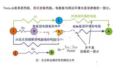
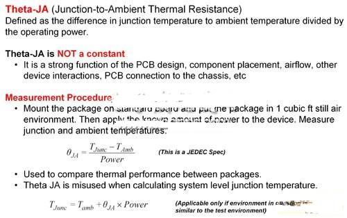
Figure 1 Electrical network Theta-JA analysis
Figure 2 Interpretation of Theta-JA
The thermal resistance (Theta JA) data is now valid for surface mount packages with leads using the new JEDEC standard. The actual data is generated on several packages, while the thermal model runs on the other packages. The data is grouped according to the package type and the Theta JA value displayed at different airflow levels.
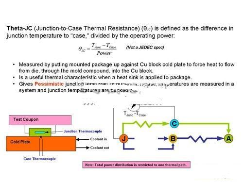
The node-to-environment data is the thermal resistance data of the node-to-shell (Theta JC) (see Figure 3). The actual Theta JC data will be generated based on the package tested using JEDEC printed circuit board (PCB).
|
Disclaimer: This article is transferred from other platforms and does not represent the views and positions of this site. If there is any infringement or objection, please contact us to delete it. thank you! |


 Business consulting

 13823761625
 Mail me