


Discussion on capacitance calculation of buck converter IC
Time:2023-03-23
Views:1038
Buck Converter
FIG. 1 is a basic circuit of a step-down converter. When the switching element Q1 is turned on, a current flows through the coil L from Vin and charges the output smoothing capacitor Co, and the output current Io is supplied to Vin. At this time, the current flowing into the coil L generates a magnetic field, and the electrical energy is converted into magnetic energy and stored. When switching element Q1 is turned off, freewheeling diode D is turned on, and the energy stored in L is then released to the output side.
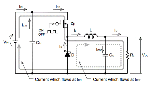
Figure 1 Basic buck converter circuit
Calculation of input capacitance
The rated voltage of the input capacitor must be higher than the input voltage. In addition, the rated ripple current of the capacitor must be higher than the input ripple current of the IC. Although the average value of the input current decreases proportionally to the transformation ratio, the same current that is momentarily equal to the output current flows through the buck converter, as shown in the IDD in Figure 2.

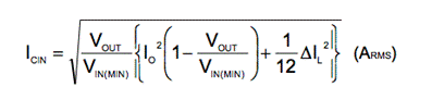
Figure 2 Current Waveform of Each Part
This will be averaged by the input capacitor, but as clearly shown by the ICIN in Figure 2, the AC ripple current flowing into the input capacitor is higher than the output ICO. The effective value of ICIN can be calculated by the following formula:
|
Disclaimer: This article is transferred from other platforms and does not represent the views and positions of this site. If there is any infringement or objection, please contact us to delete it. thank you! |


 Business consulting

 13823761625
 Mail me