


Simple reverse polarity protection circuit without voltage drop
Time:2023-03-24
Views:1034
The usual method of reverse voltage protection is to use diodes to prevent damage to the circuit. One solution is to use a series diode that allows only current to flow to the correct polarity (Figure 1). In addition, a diode bridge can be used to rectify the input, so that the circuit always has the correct polarity (Figure 2). The disadvantage of these schemes is that the voltage drop across the diode consumes energy. When the input current is 1A, the power consumption of the circuit in Figure 1 is 0.7W, and the power consumption of the circuit in Figure 2 is 1.4W. This example proposes a simple method that has no voltage drop and therefore no power consumption (Figure 3).

.jpg)
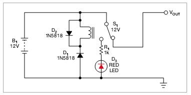
This method uses a relay to handle the reverse polarity voltage problem. For example, a 12V power supply system uses a 12V relay. When the correct polarity is applied to the circuit, D1 is reverse biased and relay S1 remains closed. The input and output power lines are normally connected to the terminals of the relay, and current flows to the final circuit. Diode D1 blocks the power supply to the relay, preventing the circuit from consuming power.
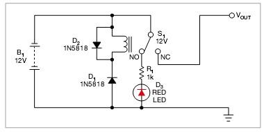
When incorrect reverse polarity is applied, the diode is biased forward, causing the relay to activate (Figure 4). The relay cuts off the power to the final circuit, and a red LED illuminates indicating a reverse voltage. The circuit consumes energy only when a reverse polarity voltage is applied. Unlike FETs or semiconductor switches, relay contact switches have a low conduction resistance, which means that there is no voltage drop between their input power supply and the protected circuit. Therefore, the design is suitable for systems with relatively tight voltage margins.
In Figure 1, a series diode protects the system from reverse polarity, but the diode consumes power.
In Figure 2, with a bridge rectifier, the system can operate normally regardless of the polarity of the input. The diode power consumption of this circuit is twice that of the circuit in Figure 1.
In Figure 3, connecting a relay switch can bypass the power supply of the system without power consumption. D2 is used for clamping the inductive inrush current of the relay coil.
In Figure 4, when the reverse input voltage is applied, the relay switch engages, cutting off the power supply to the system, and the LED emits light.
|
Disclaimer: This article is transferred from other platforms and does not represent the views and positions of this site. If there is any infringement or objection, please contact us to delete it. thank you! |


 Business consulting

 13823761625
 Mail me