


Usage of Efficient BLDC Brushless Motor
Time:2023-06-02
Views:933
Sinusoidal control is the best way to achieve these goals, but compared to more traditional trapezoidal control techniques, this control increases cost and complexity. This article will discuss the basic principles of BLDC motor control and the reasons for using sine control instead of trapezoidal control.


This article will also introduce some ready-made commercial solutions, including integrated motor drivers and controller chips, which can be used to transition to sinusoidal control more easily and accelerate the design process.
Basic Principles of BLDC Motors
The BLDC motor eliminates the requirement of using a mechanical commutator through reverse motor settings; The winding becomes the stator, and the permanent magnet becomes a part of the rotor. The windings are usually powered by six MOSFET bridges controlled by pulse width modulation (PWM), which turn in accordance with the control order to generate a rotating magnetic field, thus "dragging" the rotor around it and driving the connected load (Figure 1).
The commutation is determined by the relative position of the rotor and stator, which is measured by Hall effect sensors or by the amplitude of the back electromotive force (EMF) generated during motor rotation (limited to sensorless motors).
There are currently three electronic commutation control schemes: trapezoidal, sinusoidal, and field oriented control (FOC). The implementation cost of FOC is high and is dedicated to high-end applications, so this article will not discuss it.
For many applications, trapezoidal controlled BLDC motors are the best solution. This type of motor has a compact structure, reliable performance, and rapidly decreasing price, making it particularly suitable for many small motor applications, including automobiles, white goods, and computers.
In addition, trapezoidal technology is the easiest to implement and therefore the most popular. The motor is powered by DC per phase, every 60 ˚ Perform reversing. The phase drive is either "high", "low" or kept floating.
In theory, such a system can generate smooth and constant torque. In fact, the current of a specific phase cannot instantly change from low to high. On the contrary, the resulting rise time generates ripples in the output that are consistent with the steering timing (Figure 2).
Torque ripple is not the only drawback of trapezoidal controlled BLDC motors. Another drawback is electrical and acoustic noise. An important source of noise is the fast switching DC current that powers each phase. From an electrical perspective, this noise heats up the winding and reduces efficiency. From an acoustic perspective, the "buzzing" sound frequency generated by the switching frequency and its harmonics is not very high, but it is very harsh.
Implement sinusoidal control
Sinusoidal control is very complex, and few engineers can implement the system solely by borrowing basic principles. A better approach is to utilize the knowledge of chip suppliers to develop BLDC motor design kits. The FRDM-KE04Z of NXP is an example.
It utilizes Kinetis KE04 ARM ® Cortex ®- M0 MCU runs sine algorithm. Due to the control circuit design being based on a common BLDC driver chip, it further reduces the difficulty of implementation. These devices typically integrate PWM control and power electronics into one chip and provide an interface to external MCU. Integrating other devices into MCU can form a complete circuit with only some additional passive components.
Sine substitution method: "saddle shaped" diagram
In practice, pure sinusoidal driving voltage is rarely used because the efficiency of generating voltage for each motor terminal is low compared to grounding. A better method is to generate a sinusoidal differential voltage between phases, with a phase offset of 120 ˚ Perform reversing. The implementation method is to change the PWM duty cycle (as well as the driving voltage) relative to ground using a "saddle" diagram (instead of a sine) (Figure 3). Subsequently, the phase current of the driving motor follows a pure sine wave variation of the interphase voltage.
The saddle plot method has two advantages: firstly, the maximum differential voltage generated is higher than the voltage that can be generated by a pure sine signal, thus the given input torque and speed are also greater. Secondly, 1/3 of the time output of each terminal is zero, further reducing switching losses in the power stage.
One complication of the sine control method is that it precisely controls the duty cycle based on the motor angle necessary to form a saddle voltage input. This even becomes more difficult during high-speed rotation. The main challenge is that the motor position can only be accurately determined six times per revolution, and one of the magnetic poles of the rotor passes through one of the three Hall sensors. For example, the commonly used solution for FRDM-KE04Z is to multiply the motor angular velocity by partial T and assume that the motor velocity is constant, thereby estimating the motor angle ("mtrAngle") between Hall sensors.
Then use a query table to determine the PWM duty cycle for a specific angle. In FRDM-KE04Z, the query table provides the duty cycle for each angle of motor rotation (actual 384 increments).
This type of method utilizes the incidental effects of using saddle plots. Special note: Since the voltage value of a specific phase is zero within one-third of the time, there is no need to query during this period, which requires less processor resources and allows for the use of more common low-cost MCUs in applications.
The disadvantage of this method is that when the motor accelerates rapidly during the startup phase, the motor speed interpolation between Hall sensors is likely to be inaccurate. This can lead to uneven torque response.
A common solution adopted by the BD62011FS fan motor controller of ROHM Semiconductor to address this issue is to start the motor in trapezoidal control mode and switch to sinusoidal control after reaching a specific speed (usually 5-100 Hz), resulting in higher interpolation accuracy.
Rohm‘s equipment is mainly aimed at controlling BLDC motors equipped with Hall sensors. The chip adopts PWM control and sinusoidal commutation logic of high-voltage and low-voltage MOSFETs. It can operate within the input range of 10 to 18 V and provides an output range between 2.1 and 5.4 V (up to 1 W). The target applications include air conditioning, water pumps, and white goods.
Another design challenge is the phase delay between the given phase driving voltage and the generated sine wave current, which typically occurs in non compensated BLDC motors. The motor can operate normally, but its efficiency will decrease, which will first defeat the goal of achieving a sinusoidal control scheme. The reason for this low efficiency is not the phase delay between the driving voltage and phase current, but rather the phase delay between the phase current and the sinusoidal back electromotive force.
Fortunately, many driver chips, including ON Semiconductor‘s LV8811G power MOSFET driver, allow designers to introduce a leading phase angle in the sinusoidal driving current, ensuring that its peak is consistent with the peak of the back electromotive force. The leading phase angle is usually set to increase linearly with the input voltage, which determines the motor speed (Figure 4).
LV8811G is a three-phase BLDC motor driver controlled by a single Hall sensor and adopts sinusoidal control. Both direct PWM pulse input and DC voltage input can be used to control motor speed.
When using LV118811G, designers can set the initial conditions through the voltage divider resistors on pins PH1 and PH2: the speed at which the phase angle begins to lead and the gradient of the leading phase angle slope. Afterwards, the internal logic of the chip determines the leading phase angle of the given speed based on a predetermined formula.
Sensorless BLDC sine control
Sinusoidal control can also be achieved through sensorless BLDC motors. The operation of these motors is similar to that of motors using Hall effect sensors, except that the position information is obtained by measuring the back electromotive force.
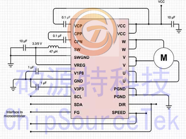
For example, Texas Instruments‘ DRV10983 is designed for sinusoidal control of sensorless BLDC motors. The chip integrates power electronic devices, which can connect to external MCUs and provide up to 2 A of continuous driving current. Sine control is achieved by using the company‘s proprietary control scheme.
In this scheme, the commutation control algorithm continuously measures the motor phase current and regularly measures the supply voltage. Then, the device uses this information to calculate the back electromotive force and motor position. The motor speed is determined by the number of times the back electromotive force of a phase crosses zero per unit time. The chip also allows for leading the phase angle to adjust the phase current and back electromotive force, thereby achieving maximum efficiency.
DRV10983 is specifically designed for cost sensitive, low noise, and low external component counting applications (Figure 5).
summary
Due to its advantages in performance and reliability, BLDC motors are gradually becoming a substitute for traditional brushless motors. For many applications, trapezoidal control can meet usage expectations, but if the designer‘s task is to improve efficiency, reduce electrical and acoustic noise, and improve torque transmission, sinusoidal control should be considered.
Although sine control increases complexity and cost, development tools, functional MCUs, and integrated driver ICs have greatly simplified the design process, making sine control more practical and simple. Moreover, the flexibility of development tools and the adaptability of driver IC enable designers to fine tune applied motors and pay more attention to product differentiation.
|
Disclaimer: This article is transferred from other platforms and does not represent the views and positions of this site. If there is any infringement or objection, please contact us to delete it. thank you! |


 Business consulting

 13823761625
 Mail me