


How to determine if your motor driver is working properly
Time:2023-10-20
Views:515
When you try to drive the motor with a newly designed PCB system, the new system may not always work properly the first time.
For example, the motor may not start or operate unevenly.
For example, the motor may not start or operate unevenly.
The debugging process includes analyzing your system and collecting information about various components. An effective way to identify the root cause of a problem is to determine whether specific functions of the system are operating as expected. Understanding the various important parameters of motor drive components can help you or your team debug problems and propose solutions.
Let‘s take a look at DRV835x, which is a series of brushless DC gate driver devices.
The following is a table of the main characteristics of the device:
| category | Design/Features | function | Related parameters |
| power supply | VM motor voltage | Provide primary voltage input for the upper electrical components, enable core IC operation, and supply power to the voltage regulator. | VM - Motor Driver Voltage |
| I_ VM - Working power supply current | |||
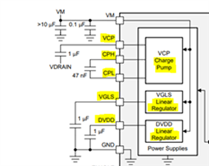
| Voltage regulator | VCP charge pump regulator | Use capacitors and switching circuits to provide higher voltage for high side gate drivers. | VCP - stored charge pump voltage output |
| CPH/CPL - Flying capacitor positive and negative pole nodes | |||
| VDRAIN or VM - Charge Pump Voltage Reference | |||
| VGLS linear regulator | Provide a~11V voltage source for the low side gate driver voltage. | Maximum input voltage | |
| inimum input voltage (voltage drop) | |||
| Current consumption and rating | |||
| consumption | |||
| DVDD linear regulator | Provide a 5V voltage source that can be used by external circuits. | External output capacitor | |
| Step-down/step-up voltage regulator | Use a switch DC/DC circuit power regulator to provide a voltage source. | Select external components such as capacitors, inductors, diodes, and switches | |
| fault detect | OVERCURRENT | The circuit protection function can be triggered when overcurrent occurs in the system. This is usually achieved by monitoring the voltage drop on the series resistor. | V_ DS - MOSFET drain source voltage |
| V_ Sense - R_ Pressure drop at both ends of sense | |||
| superheat | The circuit protection function can trigger warnings and faults when the system temperature is too high. | Device temperature | |
| PCB heat dissipation and design layout | |||
| undervoltage/overvoltage | The circuit protection function can be triggered in the event of irregular voltage. Various voltage sources and regulators in the system may have this protection. | VM - Motor Driver Input Voltage | |
| VCP - Charge Pump Voltage | |||
| VDRAIN - High side MOSFET drain voltage | |||
| VGLS - Low side gate voltage from regulator | |||
| Gate driver failure | Circuit protection function, which can monitor the gate drive voltage on GHx/GLx pins and external MOSFET gate voltage. | I_ Drive - Gate Drive Current Setting | |
| T_ Drive - gate drive timing setting | |||
| MOSFET gate source voltage (potential short circuit) | |||
| OUTPUT | Gate driver and output MOSFET | The high/low output of the driver device depends on the device input. Appropriate gate drive voltage and gate drive current settings are required to achieve excellent performance. | Gate drive voltage and current |
| Output MOSFET rating | |||
| Device specific truth table logic | |||
| Sensors and Feedback | Hall Effect Sensor | Provide feedback on the rotor position based on the magnetic field of the rotor. | Motor driver system wiring/signal wiring |
| Hall effect sensor placement | |||
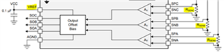
| CSA - Current detection amplifier | Monitor the current flowing through the half bridge LS. | R_ Sense - Resistor selection | |
| -Closed loop phase current feedback | ain setting for CSA | ||
| Unidirectional and bidirectional current detection | |||
| =-Implement external torque control | Motor driver system wiring/signal wiring | ||
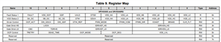
| Programmability | I2C/SPI协议 | The device can provide configurable functions by using various memory registers and programmed user settings. | Memory register address and bit value |
| The device may also have fault code storage registers for indicating the type of fault event |
Detailed description of various device functional categories:
source
•VM is the main power supply for the motor driver IC, usually biased at the voltage level of the motor.
•Under appropriate working conditions, the power supply voltage and current consumption should be within the limits of the data sheet.
•Otherwise, the device may be in an abnormal operating state, or this may indicate some degree of damage to specific samples on your circuit board.
Voltage regulator
•The purpose of a voltage regulator is to output a stable specific voltage value in the system. There are many different types of voltage regulators, such as low dropout linear regulators (LDO), charge pump regulators, and buck/boost regulators. You may need to check these functions first, as these regulators are typically crucial to other circuits in the system, such as the gate drive voltage of HS and LS MOSFETs.
•If the voltage regulator in the system does not output the correct voltage, you will need to check if the following situations occur:
• It has been turned off by the device‘s protection function or low power/sleep mode function
• The input voltage is correct and connected to the device pins
• The gate driving current setting and waveform behavior of the gate driver meet expectations
•The value of the external passive component input to the voltage regulator is missing or incorrect
•The device may be damaged internally, resulting in the regulator not functioning properly
Fault detection
•A ‘fault‘ is a detected event that indicates a problem with the current operating state of the device.
•If the motor does not work, the first thing to check is the nFault pin and fault register.
•There are many types of faults, but the main faults are related to voltage, current, and temperature. Many devices will include some type of fault detection function, which can protect the system when a fault is detected and turn off the device function to prevent further damage. To determine the specific type of fault and which fault recovery mechanism exists, please refer to the device data sheet.
Output switch
•A core function of the motor driver is the ability to control the gate driver and turn on/off MOSFETs.
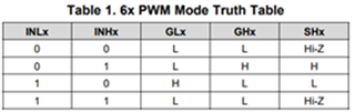
•The control logic will depend on the control interface of your device, but it is usually explained with a truth table to indicate what output any given input will produce.
•Please note that the gate drive voltage and current are crucial for the normal operation of MOSFETs.
•If your motor system encounters problems during commutation, you need to reconsider the truth table logic. For example, it may indicate the reason for a malfunction or incorrect rotation direction when the motor is started.
With/without sensor feedback
•Feedback loops involving Hall effect sensors or current detection amplifiers are typically used to detect motor position to help MCU drive the motor more efficiently.
•If your motor is not operating properly and your design includes these feedback functions, reviewing the data sheet guide can help identify issues with CSA gain settings or input signals. Improper setting may also result in erroneous alarms for overcurrent fault detection in the output MOSFET.
• In addition, it is best to check the commutation algorithm and motor wiring of the system.
Programmability
•Some motor driver ICs may be configured with memory (OTP/EEPROM) for motor settings.
•This requires a communication protocol (such as SPI or I2C) to read/write memory values in the chip and program settings. Detailed information on the settings and protocols used can be found in the specific device data sheet.
•Each memory configurable function will have a corresponding value at a specific address bit, as described in the device register mapping. Abnormal device behavior may be due to the use of incorrect settings.
•The best practice is to understand what pull-up or pull-down resistors are required on the I2C pin (SCL, SDA) or SPI pin (SDI, SDO) by reviewing the data sheet. The following links document some other general guidelines related to SPI:
• SPI configuration and usage
|
Disclaimer: This article is transferred from other platforms and does not represent the views and positions of this site. If there is any infringement or objection, please contact us to delete it. thank you! |


 Business consulting

 13823761625
 Mail me