


Current sensor magnetic field interference management
Time:2023-10-21
Views:517
This article introduces Allegro‘s ACS71x current sensor integrated circuit (IC), which does not require a concentrator and can control and reduce external magnetic field interference. These devices can improve the performance of small current differentiation through simple layout steps.

The current path in the ACS71x device. The current flows through a U-shaped loop in any direction and bypasses the Hall element (X). The U-ring is installed below the chip in the SOIC8 package.
The ACS71x series Hall effect based current sensor IC measures the current by sensing the magnetic field generated when the current passes near the Hall element (see Figure 1). They directly measure the magnetic field without the need for a magnetic concentrator, which is a common feature of other magnetic devices (such as Allegro MicroSystems CA and CB packaging for ACS75x series current sensor ICs).
The advantage of not having a concentrator is that it almost eliminates hysteresis as a source of IC error. However, this also results in poor shielding ability of ACS71x devices against external magnetic fields, which may cause distortion in current measurement. In applications where large magnetic fields may exist, attention must be paid to the alignment and spacing of Hall elements relative to these magnetic fields. In some cases, it may also be necessary to shield equipment.
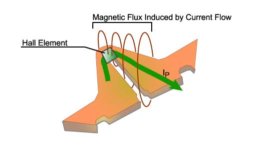
U-ring and Hall element. The current flowing through the U-shaped circuit generates magnetic lines of force in a plane orthogonal to its path. The magnetic flux perpendicular to the plane of the Hall element can generate Hall voltage.
The magnetic flux line forms a circle around the conductor in a plane perpendicular to the direction of the current flowing through it. The Hall element only responds to the magnetic flux component perpendicular to its surface and is only susceptible to the influence of the magnetic field in that direction. As shown in Figure 2, although the path of the primary current IP is in the same plane as the Hall element, the magnetic flux vector generated by the current flowing through the U-shaped circuit is perpendicular to the plane of the Hall element. The components that intersect with Hall elements will sense a voltage at both ends, which is then amplified and used to generate an output voltage.
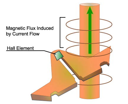
Adjacent conduction is perpendicular to the plane of the Hall element. The magnetic flux line generated perpendicular to the current is parallel to the Hall plane and does not generate Hall voltage.
If possible, the high current conductor near the device should be perpendicular to the plane on the circuit board where the device is packaged. As shown in Figure 3. Through this arrangement, the magnetic flux will cycle within the plane of the Hall element instead of passing through it, and has almost no effect on the output of the Hall IC.
|
Disclaimer: This article is transferred from other platforms and does not represent the views and positions of this site. If there is any infringement or objection, please contact us to delete it. thank you! |


 Business consulting

 13823761625
 Mail me