


Control principle of brushless DC motor and working principle of brushless DC motor
Time:2024-01-31
Views:239
01. Overview
From simple drilling rigs to complex industrial robots, many machines and equipment use brushless DC motors to convert electrical energy into rotational motion. Brushless DC motor, also known as BLDC motor, has many advantages compared to brushless DC motor. BLDC motors have higher efficiency and require less maintenance, thus replacing brush motors in many applications.
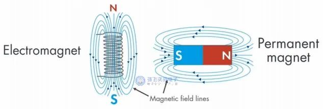
Figure 1: Schematic diagram of electromagnetic field and permanent magnetic field
The working principle of the two motors is similar, both of which generate rotational motion through the attraction and repulsion of the magnetic poles of the permanent magnet and electromagnet. But the control methods of these motors are vastly different. BLDC requires a complex controller to convert a single DC power supply into three-phase voltage, while brushless motors can be controlled by adjusting the DC voltage.
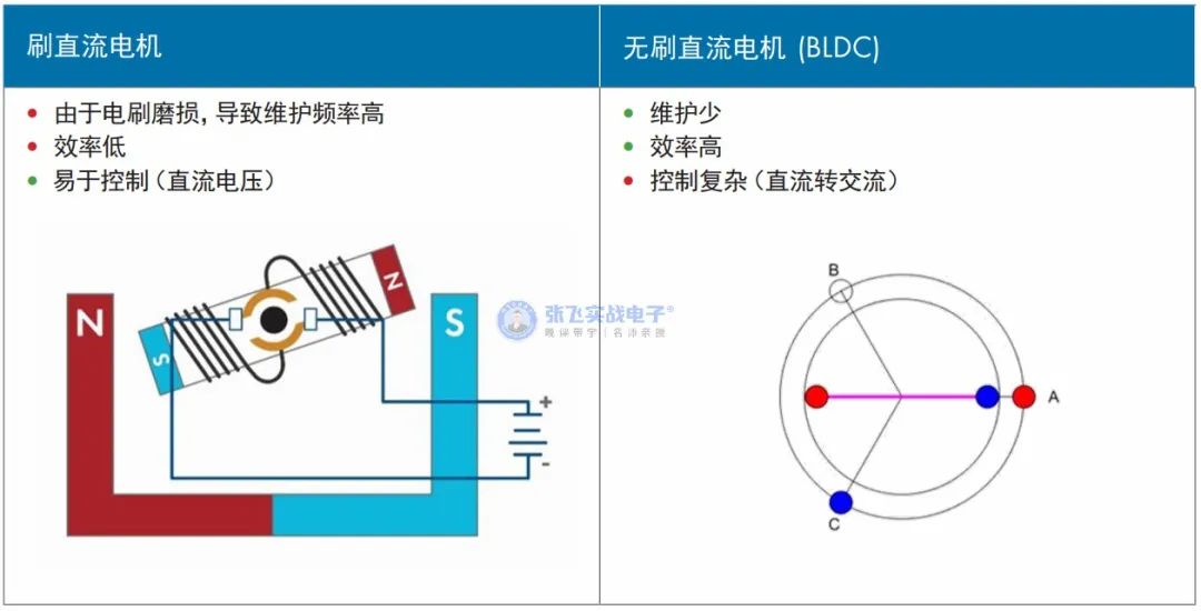
Figure 2: Comparison between Brushed Motor and DC Brushless Motor
2. Types of DC cars
2.1. Traditional Brushed DC Motors
As shown in the figure below, in a brushed DC motor, DC current passes through the coil winding of the rotor, causing the electromagnet to generate polarity. The magnetic poles of these rotors interact with the magnetic poles of fixed permanent magnets (called stators), causing the rotors to rotate.
After each half turn of the rotor, it is necessary to switch the polarity of the current in the coil winding to switch the rotor magnetic poles and maintain the rotation of the motor.
This polarity conversion of current is called commutation.
Commutation is achieved through mechanical means: every half turn of the rotor, the electrical contacts (called brushes) are connected in a loop to the commutator on the rotor.
This kind of physical contact can over time cause the brushes to wear out, resulting in the motor not working.
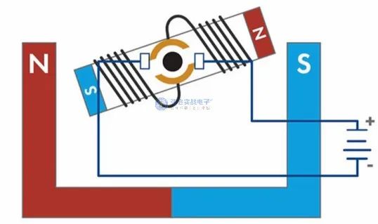
Figure 3: Schematic diagram of the working principle of a brush motor
2.2. Brushless DC motor
The BLDC motor adopts electronic commutation instead of mechanical commutation, overcoming the above-mentioned defects of brushless motors. In order to better understand this, it is necessary to further understand the structure of BLDC motors. BLDC motors are structurally opposite to brushless motors, with permanent magnets installed in the rotor and the coil winding becoming the stator.
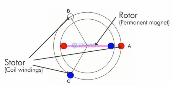
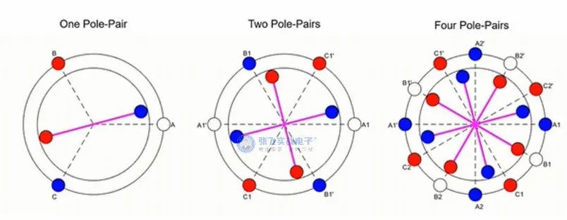
Figure 4: Schematic diagram of the working principle of brushless DC motor
The magnet layout of the motor is different, and the stator may have different numbers of windings, while the rotor may have multiple pole pairs, as shown in the following figure.
Figure 5: Schematic diagram of pole pairs for brushless DC motors
3. Simulate BLDC motor and observe the back electromotive force curve.
BLDC motors are structurally similar to PMSM, with permanent magnets placed in the rotor, and are defined as synchronous motors. In synchronous motors, the rotor and stator magnetic fields are synchronous, meaning that the rotor speed is the same as the stator magnetic field.
Their main difference lies in the shape of their back electromotive force (back electromotive force). The motor rotates like a generator. That is to say, the induced voltage generated in the stator is opposite to the driving voltage of the motor. The back electromotive force is an important characteristic of a motor, as its shape determines the algorithm required for optimal control of the motor.
The design of BLDC motors makes their back electromotive force trapezoidal, so trapezoidal commutation control is generally adopted. The trapezoidal back electromotive force of BLDC is controlled by trapezoidal commutation.
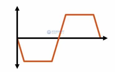
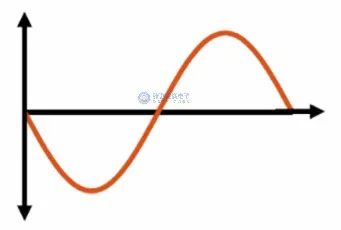
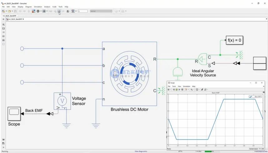
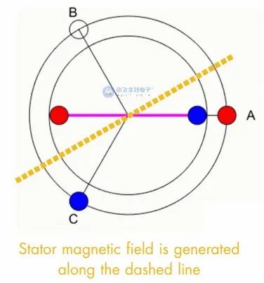
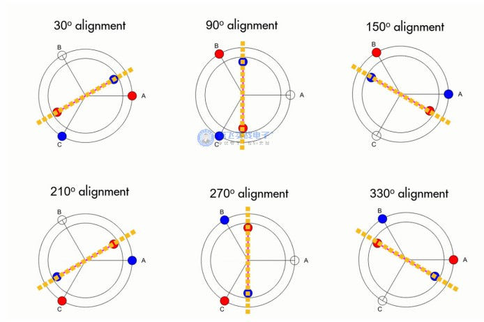
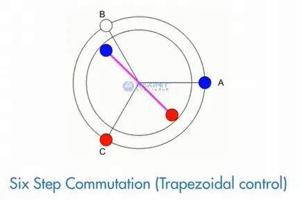
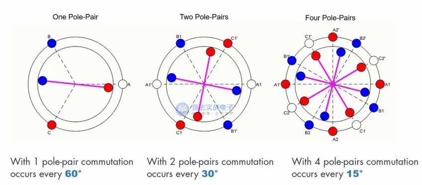
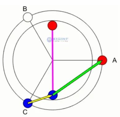
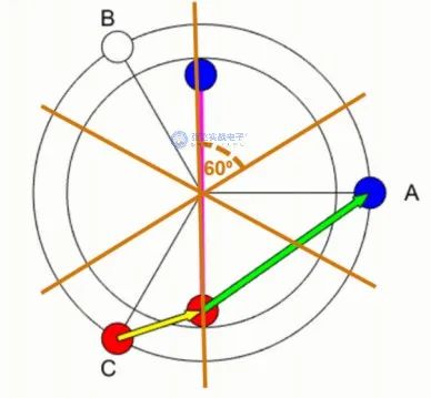
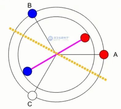
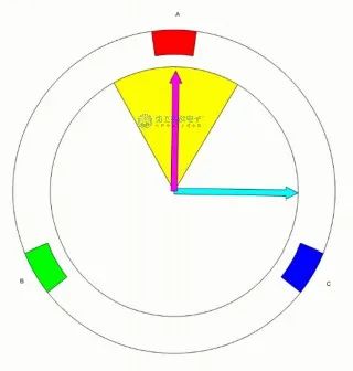
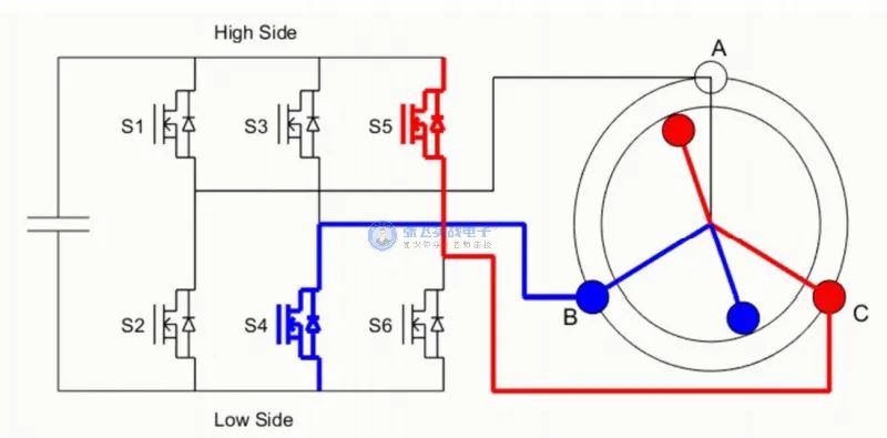
Figure 6: Schematic diagram of the back electromotive force waveform of a brushless DC motor
The back electromotive force of PMSM is sinusoidal, so magnetic field oriented control is adopted. The PMSM sine back electromotive force is controlled by the direction of the magnetic field.
Figure 7: Schematic diagram of PMSM back electromotive force waveform
In the field of motor control, the terms PMSM and BLDC are sometimes confused, which may lead to confusion in their back electromotive force curves. This article strictly defines BLDC motors as motors with trapezoidal back electromotive force.
Figure 8: BLDC motor simulation for viewing the back electromotive force waveform
In the figure, Simulink is used to simulate a single pole pair BLDC with an open terminal, i.e. no current flows through the coil. If torque is applied to drive the rotor, the electric motor will act as a generator. The variation of phase A voltage over time can be measured to observe the shape of the back electromotive force of the motor. The voltage waveform shows that the back electromotive force of the BLDC motor is trapezoidal, and the voltage in some areas is flat.
4. Six step phase transition
To better understand the behavior of BLDC motors when applying external voltage, we will use the configuration introduced earlier, where the rotor is composed of a single pole pair and the stator is composed of three coils with an angle of 120 degrees. Let the current pass through the coil and energize it (referring to phase A, phase B, and phase C). The north pole of the rotor is displayed in red
Firstly, the coil is not energized and the rotor is in a stationary state. When a voltage is applied between phase A and phase C (as shown in the figure below), a composite magnetic field is generated along the dashed line. This causes the rotor to start rotating, aligning with the stator magnetic field.
Figure 9: Schematic diagram of stator magnetic field generation (dashed line)
There are six ways for the coil to be energized, as shown in the following figure. After each phase change, the stator magnetic field rotates accordingly, thereby driving the rotor to rotate to the position shown in the diagram. In the figure below, the angle of the rotor is relative to the horizontal axis. There are six ways to align the rotor, with a difference of 60 degrees between them.
Figure 10: Schematic diagram of coil energization
That is to say, if the correct phase is reversed every 60 degrees, the motor will continue to rotate, as shown in the following figure. This type of control is called six step commutation or step control.
Figure 11: Six step reversing (trapezoidal control)
This type of motor can contain more pole pairs, but this requires more frequent commutation. In order to perform motor commutation at the correct time and phase, the controller needs to know the accurate position of the rotor at all times, which is usually measured by Hall sensors.
Figure 12: Schematic diagram of motor commutation angle for different pole pairs
5. Motor and torque generation
The arrows in the figure represent relative magnetic force, and the thickness of the arrows indicates field strength. The same magnetic poles repel each other, so the rotor rotates counterclockwise. At the same time, opposite magnetic poles attract each other, increasing torque in the same direction.
After the rotor rotates 60 degrees, the next reversal occurs.
Figure 13: Schematic diagram of magnetic field effect
By overlaying the stator magnetic field discussed earlier in the figure above, it can be clearly seen that in this commutation mode, the rotor never aligns with the stator magnetic field (yellow dashed line in the figure), but keeps chasing after the stator magnetic field.
Figure 14: Schematic diagram of stator magnetic field and rotor magnetic field
There are two reasons for using this method to change the phase in BLDC motors. Firstly, if the magnetic fields of the rotor and stator are completely aligned, the resulting torque will be zero, which is not conducive to rotation. Secondly, when the angle of the magnetic field is 90 degrees, the maximum torque can be generated. So the goal is to make the angle close to 90 degrees.
Figure 15: Schematic diagram of the angle between the rotor magnetic field and the stator magnetic field
But in BLDC motors, using six step commutation, the angle cannot be maintained at 90 degrees all the time, and the angle will fluctuate between 60 and 120 degrees, as shown in the following figure. This is because the essence of trapezoidal control is relatively simple. More advanced methods, such as magnetic field orientation control, can achieve a 90 degree angle between the stator and rotor magnetic fields, thereby generating greater torque. This method is commonly used in the PMSM control mentioned earlier.
Figure 16: Schematic diagram of the angle between the rotor magnetic field and the stator magnetic field
6. Working principle of three-phase inverter
In order to control the phase during the six step commutation process, a three-phase inverter can be used to guide direct current to the three phases, thereby switching between positive (red) and negative (blue) currents. To provide positive current to one of the phases, the high-end switch connected to that phase needs to be turned on. To provide negative current, the low-end switch needs to be turned on.
Figure 17: Schematic diagram of three-phase inverter bridge
When the angle between the rotor and stator magnetic fields is between 60-120 degrees, the three-phase inverter can maintain a uniform motor rotation by performing this operation in the above manner. To change the motor speed, the applied voltage can be adjusted. To control the motor speed without changing the power supply voltage, pulse width modulation (PWM) can be used.
|
Disclaimer: This article is transferred from other platforms and does not represent the views and positions of this site. If there is any infringement or objection, please contact us to delete it. thank you! |


 Business consulting

 13823761625
 Mail me