


How to transform solenoids and stepper motor drivers for industrial applications
Time:2024-03-09
Views:156
Author: Bill Schweber
The application of edge devices such as factory workshop control systems, automobiles, and laboratory equipment is increasingly utilizing the functions of the Internet of Things (IoT) and artificial intelligence (AI) to achieve low latency decision-making, stronger performance, lower costs, and higher security and productivity. The drivers of solenoids and stepper motors need to keep up with the times, adding more onboard sensing and intelligent functions to integrate into rapidly developing new environments, further improving accuracy, reliability, closed-loop control, cost, footprint, and ease of use.
This article summarizes the basic operations of solenoids and stepper motors, and outlines the advantages of driver ICs designed specifically for intelligent edge applications. Then, the article introduces and explains how to use the example driver of Analog Devices to start the design.
Solenoids and stepper motors: similar yet different
Solenoids and stepper motors convert current into physical motion by acting as wound coils of electromagnets. Although there are differences in appearance and function between the two, the commonality of the coils allows for the use of the same driver IC in some cases.
A solenoid is a relatively simple component that can generate linear mechanical motion by applying current. In this type of component, there is an electrical coil wound around a cylindrical tube, and there is a ferromagnetic actuator (also known as a plunger or armature) at the empty core position, which can move freely inside the coil (Figure 1, left).
In contrast, stepper motors use multiple stator coils, which are arranged in a circular pattern around the motor body (Figure 1, right). The motor rotor is also equipped with a set of permanent magnets.
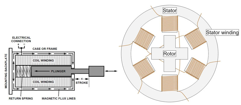
Figure 1: The structure of the solenoid includes a wound coil with an internal sliding plunger (left figure); Stepper motors are even more complex, with permanent magnets on the rotor and electromagnetic coils on the stator (as shown in the figure on the right). (Image source: Analog Devices, Monolithic Power Systems)
For solenoids, the movement of the plunger originates from a single "collision" that occurs when applying current, which will push the plunger to its limit position. After a power outage, most solenoids use springs to restore the plunger to its so-called stationary position.
In the most basic driving scheme, the solenoid is controlled by clear on/off current pulses. Although this method is simple and direct, it has many drawbacks, including high impact force, high vibration, high acoustic and electrical noise, low electrical efficiency, and almost no control over the movement or return of the plunger.
As the stator coils are sequentially energized, the resulting rotating magnetic field pulls the armature magnet, causing the stepper motor to start rotating. By controlling the timing, the rotor of the stepper motor can rotate continuously, stop, or rotate in reverse.
Unlike solenoids that do not require consideration of timing issues, the stator coils must be energized sequentially and meet the correct pulse width and other characteristic requirements.
Intelligent drives break through limitations and improve performance
By carefully controlling the current of the driving solenoid and stepper motor coils, including waveform contour shape, up and down slopes, and other parameters, intelligent drives can bring many advantages, including:
·Enhance the smoothness of movement and rotation, and minimize tremors as much as possible
·Reduce vibration and impact, especially for solenoids
·More precise positioning of stepper motor start/stop/reverse movement
·Stable performance, adaptable to transient or variable load conditions
·Improve efficiency
·Reduce physical wear and tear
·Less acoustic and electrical noise generated
·Easy to connect with monitoring processors, which is crucial for IoT facilities
The MAX22200 from Analog Devices is an integrated serial control solenoid and motor driver, demonstrating the significance of precision drives for solenoids (Figure 2). The 8 1 A half bridge drivers in this 36 V IC can be connected in parallel, doubling the driving current, or configured as full bridges to drive up to 4 blocking valves (also known as bistable valves).
.jpg)
Figure 2: Analog Devices MAX22200 is an integrated serial control solenoid and motor driver with eight half bridge drivers that can be arranged in different configurations. (Image source: Analog Devices)
This driver supports two control methods: voltage driven regulation (VDR) and current driven regulation (CDR). When using VDR, the device outputs a pulse width modulation (PWM) voltage, and its duty cycle can be programmed through the SPI interface. For a given power supply voltage and solenoid resistance, the output current is proportional to the programmed duty cycle. CDR belongs to the closed-loop control form, which is sensed by an integrated non-destructive current sensing circuit and compared with an internal programmable reference current.
Unlike simple current source drivers, MAX22200 can customize current drive distribution according to specific requirements. To optimize power management in solenoid drive applications, the excitation drive current (IHIT), hold drive current (IHELD), and excitation drive time (tHIT) for each channel can be configured separately. In addition, it also provides various protection and fault related functions, including
·Overcurrent protection (OCP)
·Load open circuit (OL) detection
·Thermal shutdown (TSD)
·Under voltage lockout (UVLO)
·Verification of Plunger Motion Detection (DPM)
The first four are well-known standard features. DPM needs further explanation. For example, in a solenoid controlled valve, if the valve operates normally when the solenoid is activated, the current distribution is not monotonic (Figure 3, black curve). On the contrary, due to the reverse electromotive force (BEMF) generated by the plunger movement, the current will decrease (Figure 3, blue curve).
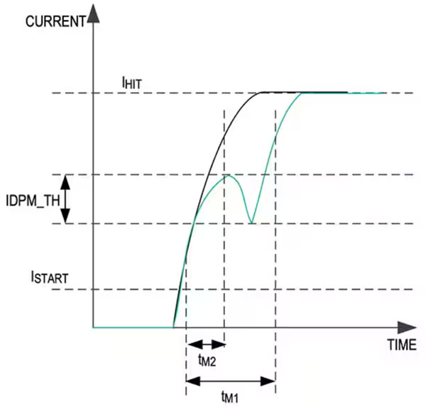
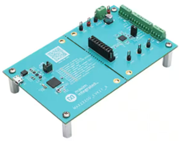
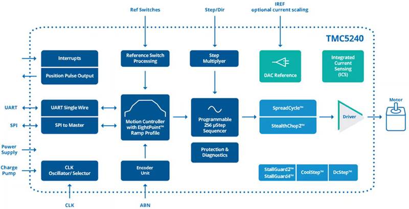
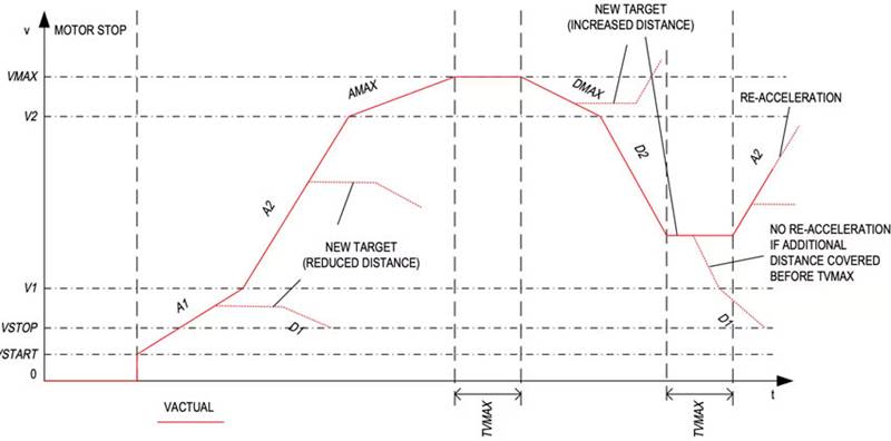
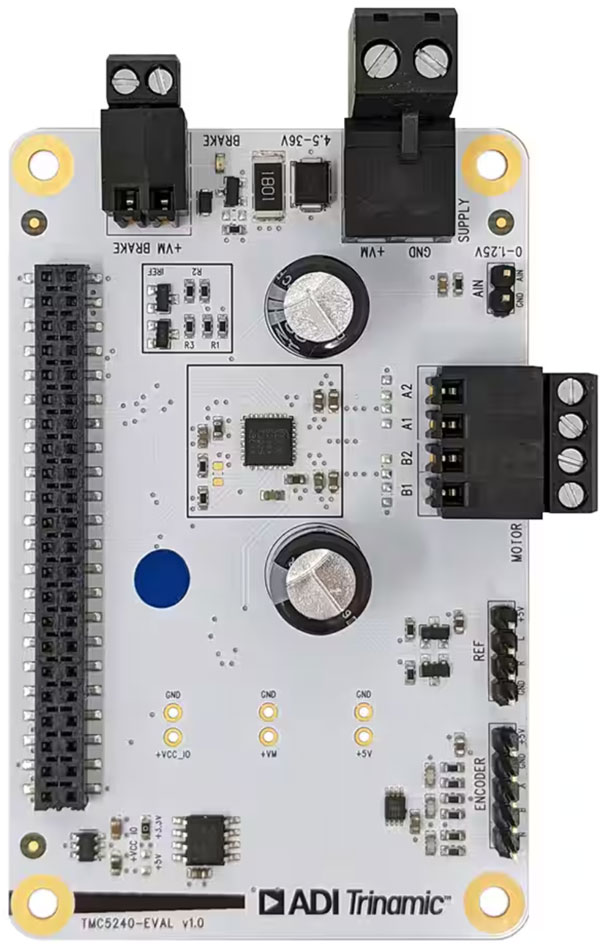
Figure 3: When driving the solenoid, MAX22200 can detect whether the solenoid or valve is stuck by judging the relationship between the expected decrease in BEMF driving current and the threshold (IDPM-TH) when the solenoid is driven from the starting current (ISTART) to the final excitation driving current (IHIT). (Image source: Analog Devices)
When set up and used for solenoids, the DPM function of MAX22200 will detect whether there is a decrease in BEMF during the excitation phase. If no drop is detected, an indication will be set in the FAIL pin and internal fault register.
Evaluation suite helps simplify processes
In order to address the performance issues of the system under different static and dynamic requirements and load conditions, Analog Devices provided the MAX22200 EVKIT # solenoid control power management evaluation board (Figure 4). This evaluation kit (EVK) supports serial control of MAX22200 and fault monitoring through onboard USB to SPI interface and MAX32625 microcontroller. It includes a Windows compatible graphical user interface (GUI) for executing the functions of MAX22200 IC, making it a complete PC based evaluation system.
Figure 4: MAX22200EVKIT # solenoid controlled power management evaluation board for MAX22200, which can fully test the IC and its load through a Windows based graphical user interface. (Image source: Analog Devices)
This fully assembled and tested circuit board can be configured as a high voltage/low voltage side solenoid, and can also be used for blocking valves (usually driven by solenoids) or brushed DC motors.
Stepper motor: higher degree of control freedom
Stepper motors are more complex than solenoids and require higher control requirements. This can be seen from the TMC5240 of Analog Devices (Figure 5), which is an integrated high-performance stepper motor controller and driver IC with serial communication interfaces (SPI, UART) and rich diagnostic functions, as well as providing embedded algorithms.
Figure 5: The TMC5240 high-performance stepper motor controller and driver IC are embedded with complex algorithms, which can help solenoids and stepper motors achieve optimal performance. (Image source: Analog Devices)
This IC includes a flexible eight point slope generator that can minimize the jerkiness in automatic target positioning. Jerk is the rate of change in acceleration, and excessive jerk can lead to many system and performance issues. This stepper motor driver integrates a 36 V, 3 A H bridge with a conducting resistance of 0.23 Ω and a non dissipative integrated current sensing (ICS). TMC5240 adopts a small TQFN32 package with a size of 5 × 5 mm and a TSSOP38 package with a heat dissipation optimization of 9.7 × 4.4 mm and bare solder pads.
TMC5240 has unique advanced features that enable higher accuracy and support high energy efficiency, high reliability, smooth motion, and low-temperature operation. These features include:
·StealthChop2: Using a noise free and high-precision chopping algorithm, the motor moves and remains quiet and silent. Compared with the simpler StealthChop, this function can achieve faster motor acceleration and deceleration
·SpreadCycle: High precision, cycle by cycle current control, capable of achieving maximum dynamic motion
·StallGuard2: Provides sensorless stall detection and mechanical load measurement for SpreadCycle
·StallGuard4: Provides sensorless stall detection and mechanical load measurement for StealthChop
·CoolStep: Using StallGuard to measure and adjust motor current to maximize efficiency and reduce heat generation of the motor and driver
Users can pre-set these functions and call them during the motor operation cycle. In addition, torque can be controlled by combining acceleration to achieve efficient and smooth acceleration and deceleration while reaching the desired value.
For example, a combination of three acceleration and deceleration stages can have two purposes: using higher acceleration values at lower speeds to adapt to the motor torque curve, or reducing jerking when transitioning from one acceleration stage to the next. For these two types of situations, the TMC5240 controller, with the eight point motion curve generator, can maintain a constant speed range while the desired target position changes in real time, thus achieving smooth mode switching (Figure 6).
Figure 6: TMC5240 provides an eight point slope that supports real-time target position changes and enables smooth mode switching. (Image source: Analog Devices)
Given the flexibility, versatility, and complexity of the driver IC, the TMC5240-EVAL evaluation board has become a popular auxiliary tool (Figure 7). It uses the standard schematic of the IC and provides multiple options in the software, allowing designers to test different working modes.
Figure 7: Using the TMC5240-EVAL evaluation board and related graphical user interfaces, designers can study and fine tune the performance of TMC5240 based on specific actuator and load combinations. (Image source: Analog Devices)
For designers with lower complexity in evaluation and design requirements, Analog Devices also offers TMC5240-BOB. This basic type IC distribution board connects the physical pins of TMC5240 to a needle socket that is easy for users to access.
summary
By adding intelligent functions to solenoid and stepper motor drivers, better control and fault detection can be provided, enabling real-time decision-making and communication with higher-level control systems or AI based productivity systems. By utilizing highly integrated drivers such as Analog Devices MAX22200 and TMC5240, users can quickly start and run advanced algorithms to optimize the performance of solenoids and stepper motors for specific applications.
|
Disclaimer: This article is transferred from other platforms and does not represent the views and positions of this site. If there is any infringement or objection, please contact us to delete it. thank you! |


 Business consulting

 13823761625
 Mail me