


ZH1121A Product Introduction:
Functional characteristics
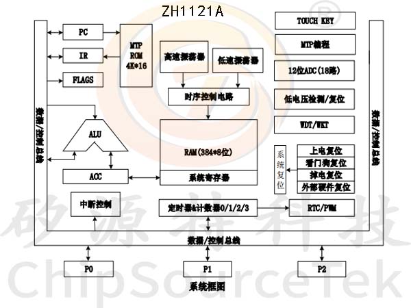
*High Performance Reduced Instruction Set Control Processing
-Based on 1T RISC CPU core
-CPU running speed can reach up to 16MHz
*Storage
┄ ROM(MTP):4K*16
┄ SRAM:384 *8
┄ EEPROM:128*8
*Clock system
*Clock system
┄ Internal high-speed clock: 32MHz/16MHz RC
┄ Internal low-speed clock: 128KHz RC
┄ External high-speed crystal oscillator: 16MHz
┄ External low-speed crystal oscillator: 32KHz RC
*Working mode
┄ Normal mode: High and low speed clocks working simultaneously
┄ Low speed mode: Only the low speed clock operates
┄ Sleep mode: Both high and low speed clocks stop working
┄ Green mode: awakened periodically by a timer
*Low voltage reset (BOR)
┄ The reset voltage is available (1.8-4.0V), with a total of 8 selectable levels
┄ The default value is the value selected by the user when burning the Code Option
*16 level optional low voltage detection module (BOD)
*Interrupt source (INT)
┄ 19 internal interrupts: T0, T1, T2, T3, T1PWM duty cycle interrupt, T2PWM duty cycle interrupt, T2CAP interrupt, UART, WKT, ADC, LVD, CMP
┄2 external interrupts: INT0, INT1
┄ 1 interrupt entry point
*GPIO
┄ Up to 18 bidirectional independently controllable I/O ports, capable of independently setting up and down resistors, and can be set as open drain outputs
┄ The IO port source driving capability is divided into two levels of control
┄ All IO have high current drive capability (60mA)
┄ All IO can be used as LCD COM output for 1/2 BIAS
*Timer
┄ T0:Basic 8-bit timer/counter, supporting pre division function.
┄ T1:16 bit configurable timer/counter (up to 32MHz)
4 sets (8 channels) of PWM, all supporting complementary outputs and adjustable dead zones
Supports pre frequency division function
Counter register configurable
┄ T2:Automatic loading of 16 bit timer, 2-channel PWM output (without complementary function) or 2-channel capture input function
┄ T3:16 bit configurable timer, supporting pre division function
*WDT
┄Supports pre frequency division function
┄Configurable overflow reset or wake-up
*WKT
┄Supports pre frequency division function
┄The CPU can be awakened in either sleep mode or green mode (IDLE)
*UART
┄ 1 independent UART communication port
*TK
┄ 18 channel high sensitivity and high reliability touch circuit, without the need for external capacitors
┄ High sensitivity can adapt to touch applications that require high sensitivity, such as remote button touch and proximity sensing
┄ High reliability with strong anti-interference ability, can pass 10V dynamic CS testing
┄ It can achieve various applications such as 18 touch buttons and derivative functions such as scroll wheels, sliders, etc
┄ High flexibility development software library support, low development difficulty
┄ Automated debugging software support, intelligent development
┄ Low power touch mode, the overall power consumption of the chip can be as low as 11uA when awakened by a single touch button
┄ In sleep mode, it supports up to 4 keys of hardware automatic scanning and can wake up the chip
┄ Built in Shield Driver
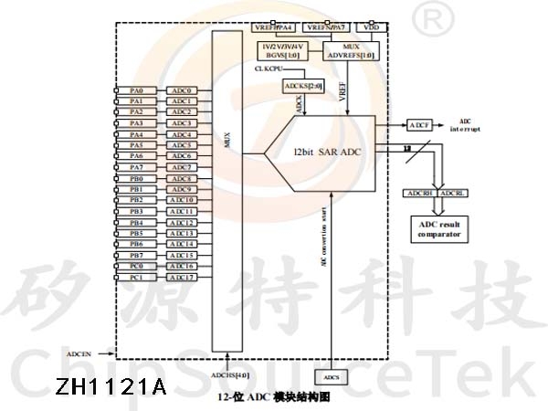
*ADC
┄ 18 channel 12 bit SAR ADC
┄ Built in reference voltages of 1.024V, 2.048V, 3.072V, and 4.096V
┄ ADC‘s reference voltage can be selected as VDD, internal reference, or external reference
┄ Internal ADC can directly measure VDD/4 voltage
┄ Internal ADC can directly measure IO/4
┄ Internal GND voltage detection
┄ Internal reference voltage detection in the internal circuit
┄ Internal two channel operational amplifier output detection
┄ ADC conversion completion interrupt can be set
*4-way operational amplifier/comparator
┄ Supports internal PGA 16x magnification
┄ Supporting operational amplifier output to ADC
*Low power consumption characteristics
┄ Sleep standby current: When the voltage is 2.5V, the typical value is 500nA
┄ Working current:
--When the frequency is 8MHz and the voltage is 3V, the typical value is 700uA
-- When the frequency is 32KHz and the voltage is 3V, the typical value is 150uA
┄ Watchdog timer current: When the voltage is 2.5V, the typical value is 1uA
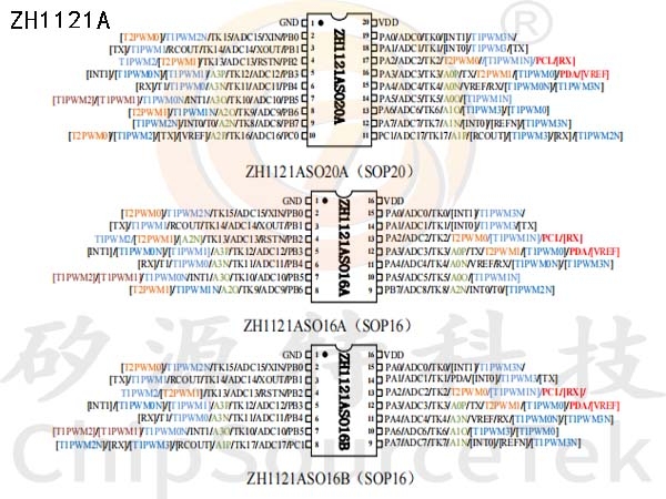
*Package: SOP16/SOP20/TSSOP20
ZH1121A System Block Diagram:
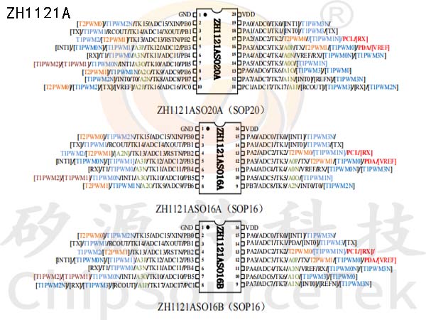
ZH1121A Pin configuration:
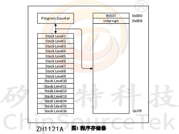
ZH1121A Program Memory (CODE):
(1)Program memory ROM
The program memory is mainly used for storing instructions. In ZH1121A, the program memory is a 4K * 16bit program MTP, which provides 1000 burnings. For specific operations, please refer to the following chapter<MTP Self Programming Module>.The reset address of the system is 0x000.
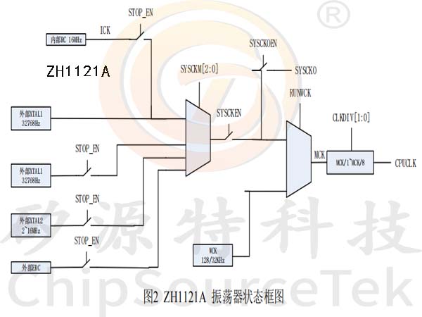
ZH1121 Aclock system:
Features
ZH1121A has two clock sources. One is an internally integrated clock ICK (16MHz), and the other is an external clock. Selected by code options CPU runs internal or external clocks.
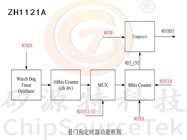
ZH1121A Watchdog (WDT):
Features

The watchdog timer (WDT) is used to prevent the program from losing control due to certain uncertain factors. When WDT starts, the CPU will reset after the WDT timing timeout. The running program usually resets the WDT before resetting the CPU. When certain faults occur, the program will be reset to normal state by WDT, but the program will not reset WDT.
When the user sets WCKEN to 1, the internal watchdog timer oscillator (128KHz) will start, and the generated clock will be sent to the "16 bit counter" for clock division. The user selects different clock division coefficients based on WDTS [3:0] to send to the subsequent "8 bits counter". When the user sets WDTEN, the "8 bit counter" starts counting, and the output of the "8 bit counter" is the internal signal WDT_ CNT [7:0]. When WDT_ When the value of CNT is equal to the value of WDTR, the watchdog overflows. When overflowed, it will send a WDTRF signal to reset the CPU and set the WDTRF flag. Users can clear the dog by setting the WDTCLR bit of WDTM.
ZH1121A ADC Way of working:


 Business consulting

 13823761625
 Mail me