APT540is Description:
APT540is a 40 Sec Easy Use Speech IC .It Support PWM or DAC voice output with high quality speech , There are 40 second Voice Length under 6 KHz sampling and 4 bit hardware compression.
Its internal built-in a oscillator for system clock without an external resistor. Maximum 63 voice groups. One Group contain several steps(voice section ); Maximum 700 steps for all the Groups. Each Step can be define Trigger Mode, Output Status, Voice Section, Mute length, I/O Type & Simple Programming Function.
User can select 8bit / 5bit / 4bit data compression. Support three mode trigger IC (Stand Alone, Serial Trigger Mode, CPU Command Mode ). Easy use development system is for function selection and voice combination . PC download the ROM code by the USB Port .
APT540is Functions
MAX voice file : 700
MAX Trigger Groups : 63
Power On Trigger Group :1
MAX Step : 700
Signal step mute length : 0.64 s ( 6k sample rate )
Operating Voltage range: 2.4V ~ 4.5V
Total Voice Duration : 40” (120K Samples)
I/O pin : 8
Voice output : PWM or DAC
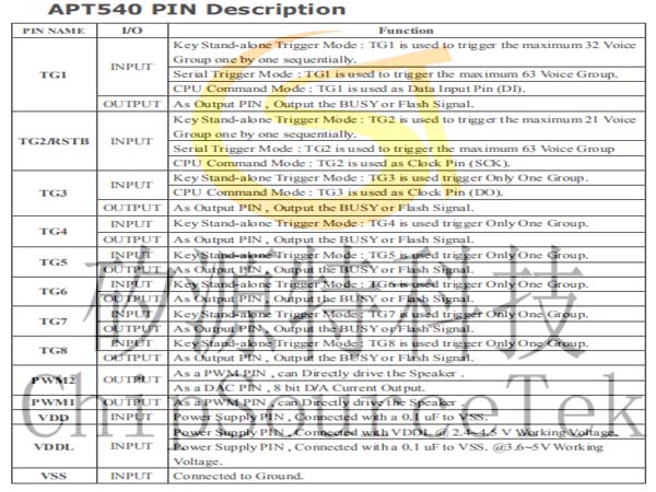
Sequential Key : TG1 -> 32 Groups.
TG2 -> 29 Groups.
TG3~TG8-> 1 Group
Debounce time : 50 us or 10 ms
On/Off function : only for all TG PIN
Sequential Key for Volume control function.
Step can change Trigger I/O Type, Trigger Mode & Output Status.
Hardware Trigger Group Repeat function.
Simple Programming Function :
(a) Write data to working register.
(b) Working Register Increasing.
(c) Step Jump by Working Register / Volume Status.
Three Mode Trigger IC :
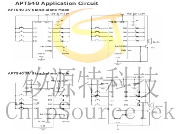
- Key Stand-alone Trigger Mode :
A. Edge/Level
B. Hold/Unhold
C. Retrigger/Irretrigger
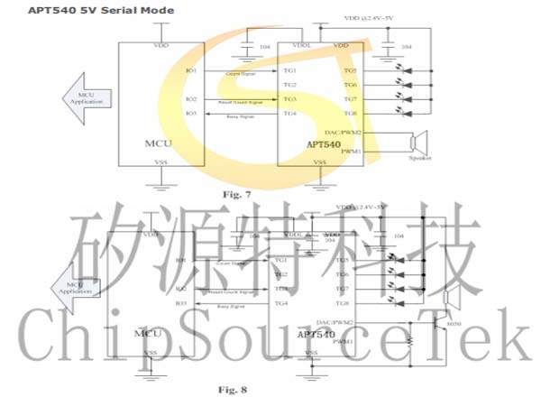
- Serial Trigger Mode :
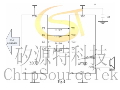
Combinations of TG1 and TG2 to trigger maximum 63 Voice Group.
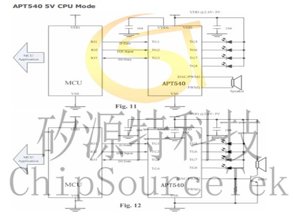
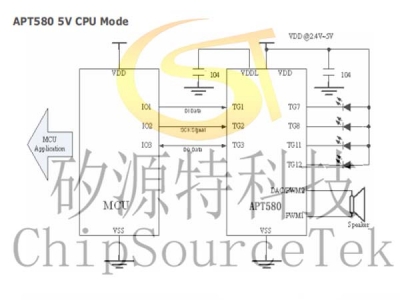
- CPU Command Mode :
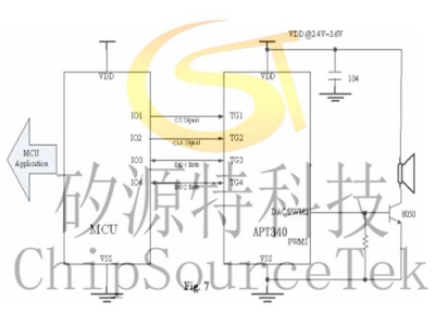
User command through TG1,TG2,TG3 with SPI CPU Interface to control the Multi-Playback function.
Output status (for each Output pin):
A. Stand by Status. (High/Low Status)
B. Busy Low Active.
C. Busy High Active.
D. LED Flash at 6 Hz.
E. LED Flash at 3 Hz.
F. LED Flash at 1.5 Hz.
G. LED Flash at 0.75 Hz.
H. PWM for LED Dimming Control.
Play rate level :
APT540 can provide different play rate in one code as follow below Reference Sample Rate.
3K, 3.2K, 3.31K, 3.42K, 3.55K, 3.69K, 3.84K, 4K, 4.17K, 4.36K, 4.57K,
4.8K, 5.05K, 5.33K, 5.64K, 6K, 6.4K, 6.85K, 7.38K, 8K, 8.72K, 9.6K,
10.66K, 12K, 13.71K, 16K, 19.2K, 24K.
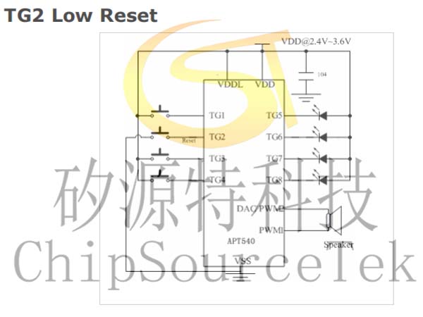
TG2 Low Reset
TG3 Volume Control
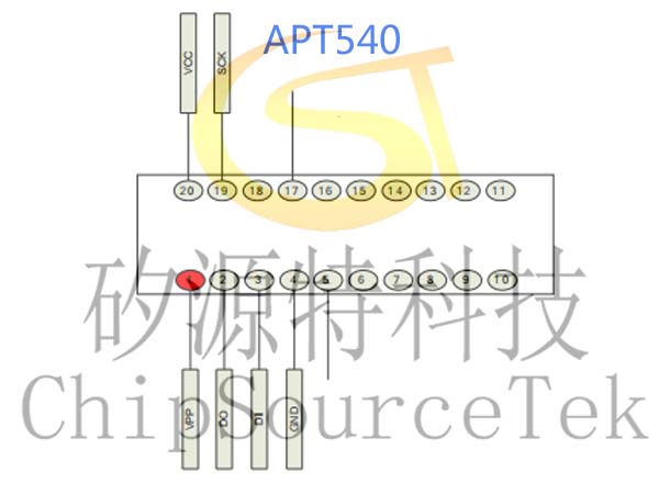
APT540 Pad Location:
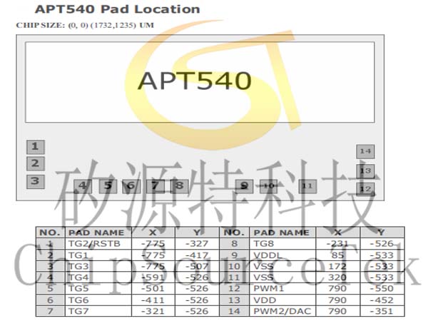
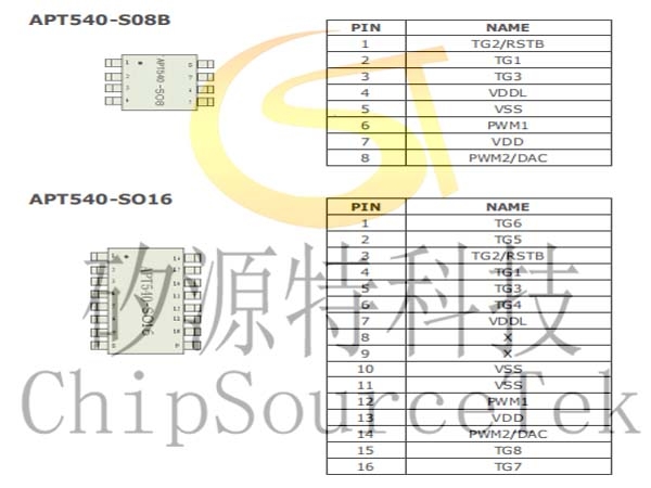
APT540 PIN Descriptions:

APT540 TG2 Low Reset:

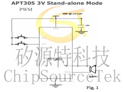
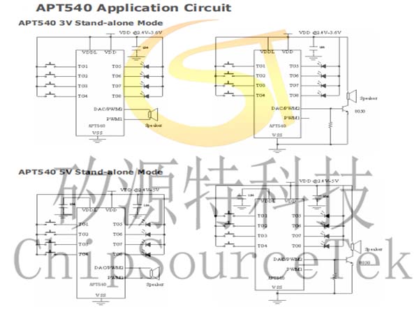
APT540 Application Circuit:
APT540 3V Stand-alone Mode

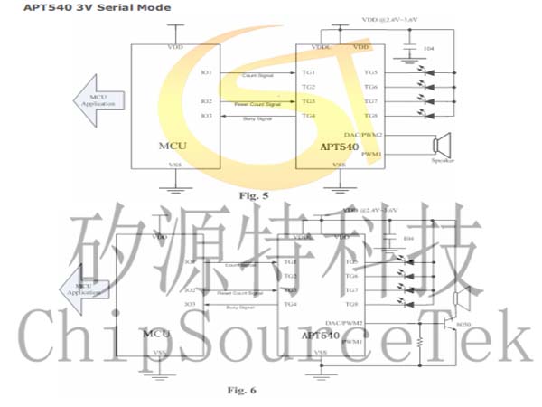
APT540 3V Serial Mode
APT540 5V Serial Mode
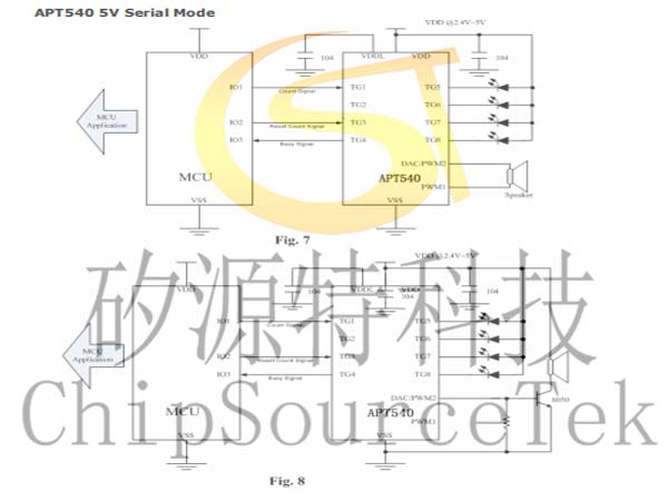

APT540 5V Serial Mode

APT540 3V CPU Mode
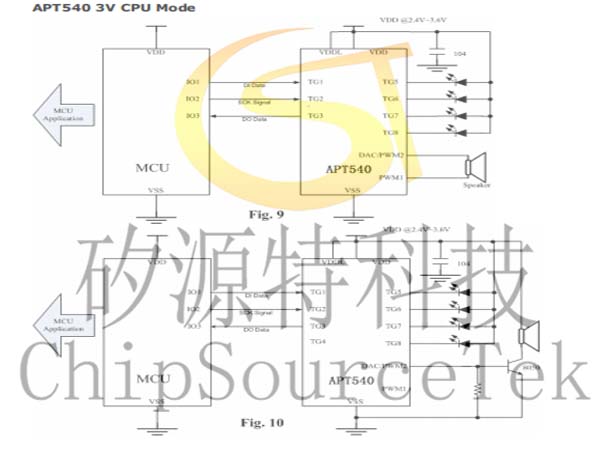

APT540 5V CPU Mode


APT540 Package Information:


Writer Board Slot Location (DIP20):
