


CST6118 Introduction:
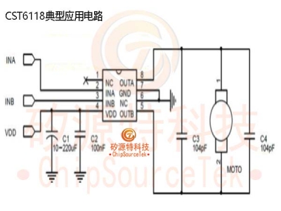
CST6118 is a single channel brushless DC motor driver chip. The maximum continuous output current can reach 1.8A, and the peak value can reach 2.5A. The chip is equipped with a power MOS full bridge driver, which can drive forward, backward, stop, and brake functions. At the same time, it is equipped with an overtemperature protection circuit to ensure the safety of chip operation。
The full bridge driving architecture and driving method can save peripheral filtering circuits, save costs, and facilitate applications. The extremely small static power consumption of the circuit (less than 1uA) can make the application range of CST6118 more extensive。
CST6118 Advantage:
Adopting a single channel full bridge power drive structure
Working voltage range (1.5V~7V)
Maximum continuous output current can reach 1.8A
Maximum peak output current can reach 2.5A
Including forward/reverse/stop/brake functions
Extremely low quiescent current (typical:0.1uA)
Low ON resistance(0.4Ω/1000mA)
Built in thermal protection function with hysteresis effect (TSD)
Package:SOP8
CST6118 Application:
DC brush motor drive for toys
Electric toothbrush
Smart lock
CST6118 Order Information:
|
Part No. |
Package |
Mark* |
Tape/Reel |
|
SOP8 |
CST-LOGO: TXXXX |
4000/Reel |
|
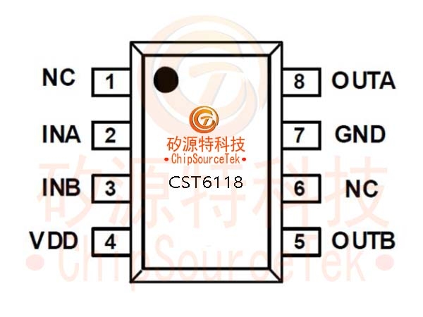
|
Number |
Name |
input/output |
Pin illustrate |
|
|
1 |
NC |
-- |
NC |
||
|
2 |
INA |
I |
Control signal A input terminal |
||
|
3 |
INB |
I |
Control signal B input terminal |
||
|
4 |
VDD |
I |
Power |
||
|
5 |
OUTB |
O |
Drive B output |
||
|
6 |
NC |
-- |
NC |
||
|
7 |
GND |
I |
GND |
||
|
8 |
OUTA |
O |
Drive B output |
||
.jpg)
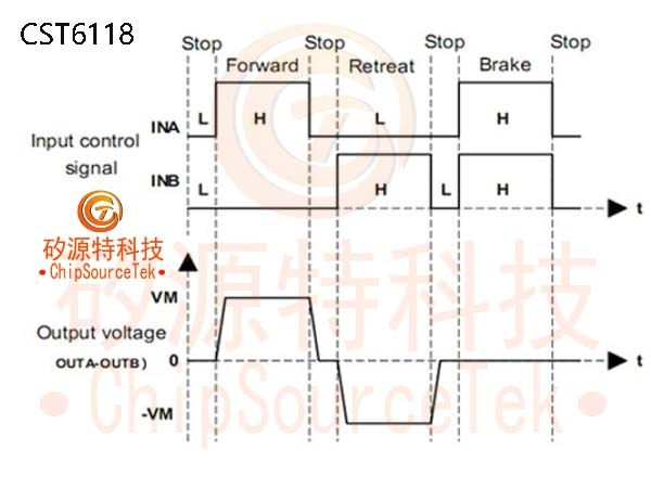
CST6118 Function Description:
|
INA |
INB |
OUTA |
OUTB |
Function |
|
L |
L |
Hi-Z |
Hi-Z |
Standby |
|
H |
L |
H |
L |
Forward |
|
L |
H |
L |
H |
Retreat |
|
H |
H |
L |
L |
brake |
CST6118 Typical waveform:
.jpg)
.jpg)
.jpg)


 Business consulting

 13823761625
 Mail me